Mounting the alpha™ series remote siren amplifier – Whelen ALPHA24R User Manual
Page 2
Page 2
Mounting the Alpha™ Series Remote Siren Amplifier
1.
Locate a suitable mounting location for the Alpha. The vertical wall between the trunk and the passenger compartment is
often a good choice and is the method discussed in this manual.
2.
Be sure that the remote amplifier fits properly and does not interfere with any parts of the trunk lid or seat back.
3.
Position the remote amplifier on the proposed mounting location. Using an awl or other suitable tool, scribe the mounting
surface where the mounting holes are to be drilled.
CAUTION! As mounting the Alpha will require drilling, it is absolutely necessary to make sure that no other vehicle
components could be damaged by the drilling process. If any vehicle component could suffer any potential harm,
select a different mounting location.
4.
Carefully drill the mounting holes using a drill bit sized for a #8 sheet metal screw.
5.
Using the supplied #8 x 5/8” sheet metal screws, secure the remote amplifier to the vertical trunk wall.
Wiring the Alpha Series Siren Amplifier (6-position connector)
Connecting to Power:
1.
Extend the RED and BLACK wires through the firewall and into the engine compartment.
2.
Follow the factory wiring harness towards your vehicle’s battery.
WARNING! All customer supplied wires that connect to the positive terminal of the battery must be sized to supply at
least 125% of the maximum operating current and FUSED at the battery to carry that load. DO NOT USE CIRCUIT
BREAKERS WITH THIS PRODUCT!
3.
Connect the RED wire to one end of a user supplied fuse block. Do not connect this unit to the battery yet!
4.
Connect the BLACK wire directly to the NEGATIVE battery terminal.
Connecting to Your Speaker (100 watt):
1.
Route the YELLOW and BROWN wires along the factory wiring harness towards your speaker.
2.
Connect the YELLOW wire to the POSITIVE (+) terminal on the speaker.
3.
Connect the BROWN wire to the NEGATIVE (-) terminal on the speaker.
Wiring the Alpha Series Siren Amplifier (9-position connector)
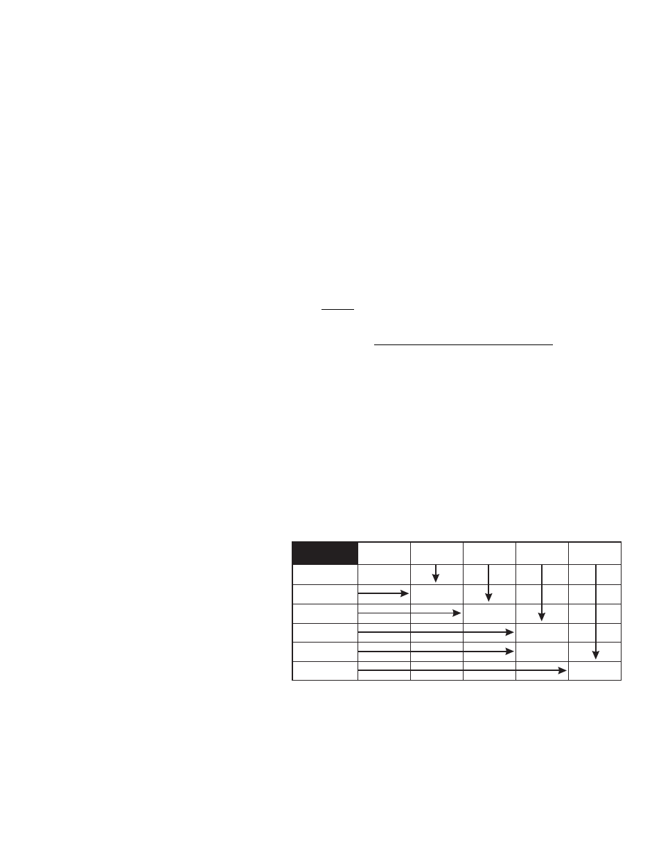
The Alpha series siren configuration and functionality are determined by the user supplied switches connected to the Alpha
amplifier. A brief explanation of each of the function wires of the 9-position connector will serve as a guide to help determine the
best configuration for your specific needs:
RED
Provides current for customer supplied switch operation (0.5 amp max.).
WHITE/GREEN
Connects to a user supplied horn transfer switch
(Fig. 1) enabling the vehicle horn ring to control
the siren.
WHITE/BROWN
Activates the Wail tone.
WHITE/RED
Activates the Yelp tone.
NOTE: Connecting both the WHITE/BROWN
and WHITE/RED wires activates the Piercer™
tone.
WHITE/ORANGE
Enables Hands-Free operation.
WHITE/YELLOW
Activates Air Horn tone.
The installation of your Alpha series siren amplifier will be complete after the fuse block wire is connected to the POSITIVE
(+) terminal of the battery. After this connection has been made, visually inspect the fuses at the back of the amplifier and at the
battery. If either of these fuses is blown, carefully inspect all of the circuit wires and make sure they are wired correctly. Replace
the blown fuses with ones of an identical amp rating as the original. If these fuses blow after installation or activation, contact
Whelen Engineering Technical Support.
+ Battery
Terminal
+ Battery
Terminal
+ Battery
Terminal
+ Battery
Terminal
+ Battery
Terminal
WAIL
WHITE/YELLOW
WHITE/RED
WHITE/BROWN
WHITE/BROWN
& WHITE/RED
YELP
AIRHORN
PIERCER
or Hi/Low
WHITE/ORANGE
WHITE/GREEN
HANDS FREE
MODE
ACTIVATION
HANDS FREE
MODE
EMABLED
TONE CONTROL
TABLE