Measuring active power (w) / power factor (pf) – Amprobe ACD-50NAV ACD-51NAV ACDC-52NAV ACD-53NAV ACD-54NAV Navigator-Clamps User Manual
Page 18
12
Measuring Active Power (W) / Power factor (PF)
1. Single Phase Power Measurement
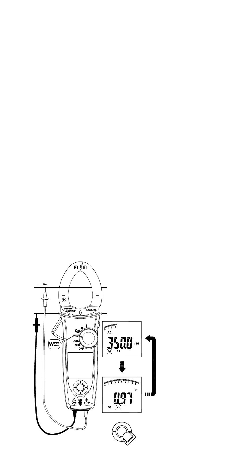
Step1. Set the rotary switch to the “W” position.
Step2. Connect the Red test lead to the Line conductor, and the Black
test lead to the Neutral conductor.
Step3. Press the trigger to open the transformer jaws and clamp one
conductor only, make sure that the jaw is firmly closed around the
conductor.
Step4. Using the Navigator key to choose the “W/PF” mode.
Note :
• The “ + ” symbol on the jaw must face on the power source side.
• In AutoSense mode, the meter will displays ACW/DCW depends on if
there is AC frequency detected.
• ACD-50NAV, ACD-51NAV and ACD-53NAV offer AC power
measurement mode only.
Active power sign :
No sign : Indicates the power flows from the power source to the load.
“_” sign : Indicates the power flows from the load to the power source.
Power factor sign :
No sign : The phase of the current signal is lagging behind the voltage
signal (inductive load).
“_” sign : The phase of the current signal is leading the voltage signal
(capacitive load).
Overrange display :
OL.U : Voltage overload
OL.A : Current overload
OL.UA : Both Voltage and current overload.
± OL kW : Active Power > 1000 kW or < -1000 kW.
ENTER
600V
600A
+L
-N
"PF"
"W"