Figure 5 – Amprobe FG2C-UA FG3C-UA User Manual
Page 13
7
Triangle, square, and sine waves
(1) Select the Function (8) , select the Range (7), and rotate the FREQUENCY (13) knob to set the required
frequency (read output in display window (4) ).
(2) Connect the Output (22) terminal to the oscilloscope for observing the waveform signal.
(3) Rotate the AMPL (12) knob to control the waveform amplitude.
(4) If attenuation of the output signal is required, pull out the AMPL (12) knob to obtain 20dB attenuation or press
the ATT -20dB (12a) button for additional 20dB attenuation..
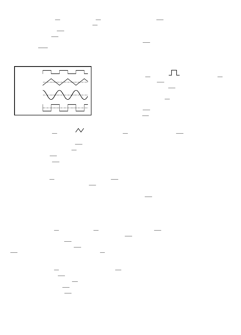
(5) The phase-relation of Output waveform and TTL output is shown in Figure 5 below:
Figure 5
TTL PULSE 0V
TRIANGLE 0V
SINE 0V
SQUARE 0V
Pulse wave generation
(1) Press the Function (8) button (
), select the Range (7),
and rotate the FREQUENCY (13) knob to set the frequency.
(2) Connect the OUTPUT terminal (22) to the oscilloscope for
observing the output signal.
(3) Pull out and rotate the Duty (9) knob to adjust the width of
pulse waveform.
(4) Adjust the AMPL (12) knob to control the pulse amplitude.
(5) Pull out the AMPL (12) knob to attenuate the output signal by 20dB.
Ramp wave generation
(1) Press the Function (8) button (
) , select the Range (7) , rotate the FREQUENCY (13) knob to set the
frequency.
(2) Connect the OUTPUT terminal (22) to the oscilloscope for observing the output signal.
(3) Pull out and rotate the Duty (9) knob to adjust the slope of ramp waveform.
(4) Adjust the AMPL (12) knob to control output amplitude of ramp waveform.
(5) Pull out the AMPL (12) knob to attenuate the output signal by 20dB.
TTL/CMOS signal output
(1) Select the Range (7) , and rotate the FREQUENCY (13) knob to set the frequency.
(2) Connect BNC connector of TTL/CMOS (20) to oscilloscope to observe the output signal.
(3) The output is a square waveform fixed at TTL level, suitable for general TTL integrated circuits.
(4) If a square waveform of CMOS level is required, pull out the CMOS (10) knob and adjust to required voltage
levels.
Variation of external voltage-controlled frequency (VCF) (FG3C-UA only)
This mode of operation allows the user to adjust the frequency of the Function Generator with an external DC
control Voltage.
(1) Select the Function (8), select the Range (7), and rotate the FREQUENCY (13) knob to set the required frequency.
(2) Connect external control voltage (0 ± 10VDC) to the VCF (21) terminal via a suitable lead, and observe the signal
generated from the Output (22) BNC terminal.
(3) Other adjustments; the AMPL (12) knob can change the amplitude of signal, or attenuate the signal; the Offset
(11) knob is for DC level changes, rotate the Duty (8) knob to change the output ratio of pulse or ramp waveform etc..
Sweep (internal) (FG3C-UA only)
(1) Select the Function (8) button and select the Range (7).
(2) Connect the OUTPUT (22) terminal to the oscilloscope channel 1 for observing the OUTPUT signal.
(3) Connect the rear panel GCV (23 ) terminal to the oscilloscope channel 2 for observing sweep control signal.
(4) Rotate the FREQUENCY (13) knob to determine the upper output sweep frequency.
(5) Pull out the FREQUENCY (13) knob to activate sweep operation.