Amprobe Telaris-Earth-Test Earth-Resistance-Tester User Manual
Page 16
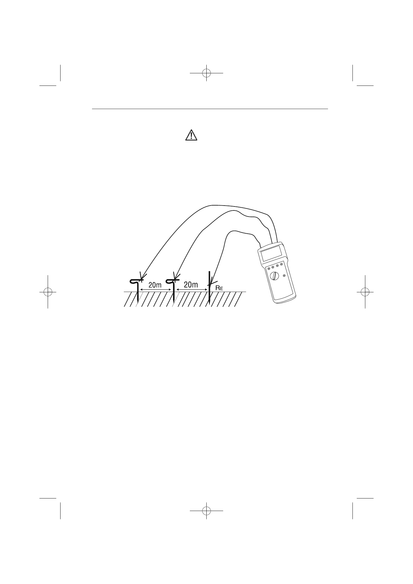
Earth Resistance Measurement (three-wire method)
• To perform this measurement the user requires the Earth Measurement Set (Cat. No.1048)
WARNING
The three-wire method consists of inserting two earth rods (one auxiliary earth and one
probe) into the soil, at a minimum distance of 20m. This layout can also be realized by
triangular shape. The test current is fed between auxiliary earth and earth. The voltage drop
between earth and probe is measured. The test lead resistance from measurement instrument
to earth is included in the measurement. This measurement is used to determine e.g. earth
resistance of foundation earths, building site earths and lighting protection earth
connections.
Figure 4: three-wire measurement
1)
Locate earth rods for auxiliary ground, probe and ground, in one line if possible, as
described in figure 4. The layout can also be realized by triangular shape. Distance
between probe and earth, or probe and auxiliary earth must be at least 20 m. The test
leads should not be parallel to each other and should not cross to avoid couplings.
2)
Connect test leads to earth rods acc. figure 4.
3)
Select "3 pole" measurement by using measurement selection switch (13).
4)
Set contact voltage (11) by using key “UL“ (14).
5)
If required choose maunal frequency selection by using key “auto/man” (16), and
select test frequency with key “f1/f2” (12).
6)
Press key “Start“ (14)
7)
Read measurement result from display.
14
H
S
E
PAEB30872261:Layout 1 12.12.2007 12:06 Uhr Seite 14