Amprobe Telaris-Earth-Test Earth-Resistance-Tester User Manual
Page 17
15
8)
To verify the measurement, exchange the connections of probe and auxiliary earth or
move the earth rod for the probe approx. 1...2m towards the earth connector (or
afterwards towards the auxiliary earth) and measure again. If the instrument shows
similar measurement results for all three measurement layouts, the probe is located
outside the voltage funnel generated by earth and auxiliary earth in the reference
earth area.
Are the measurement values not similar the probe could be located inside the voltage funnel.
To avoid this there are two possibilities:
A:
increase the distance between earth and auxiliary earth
or,
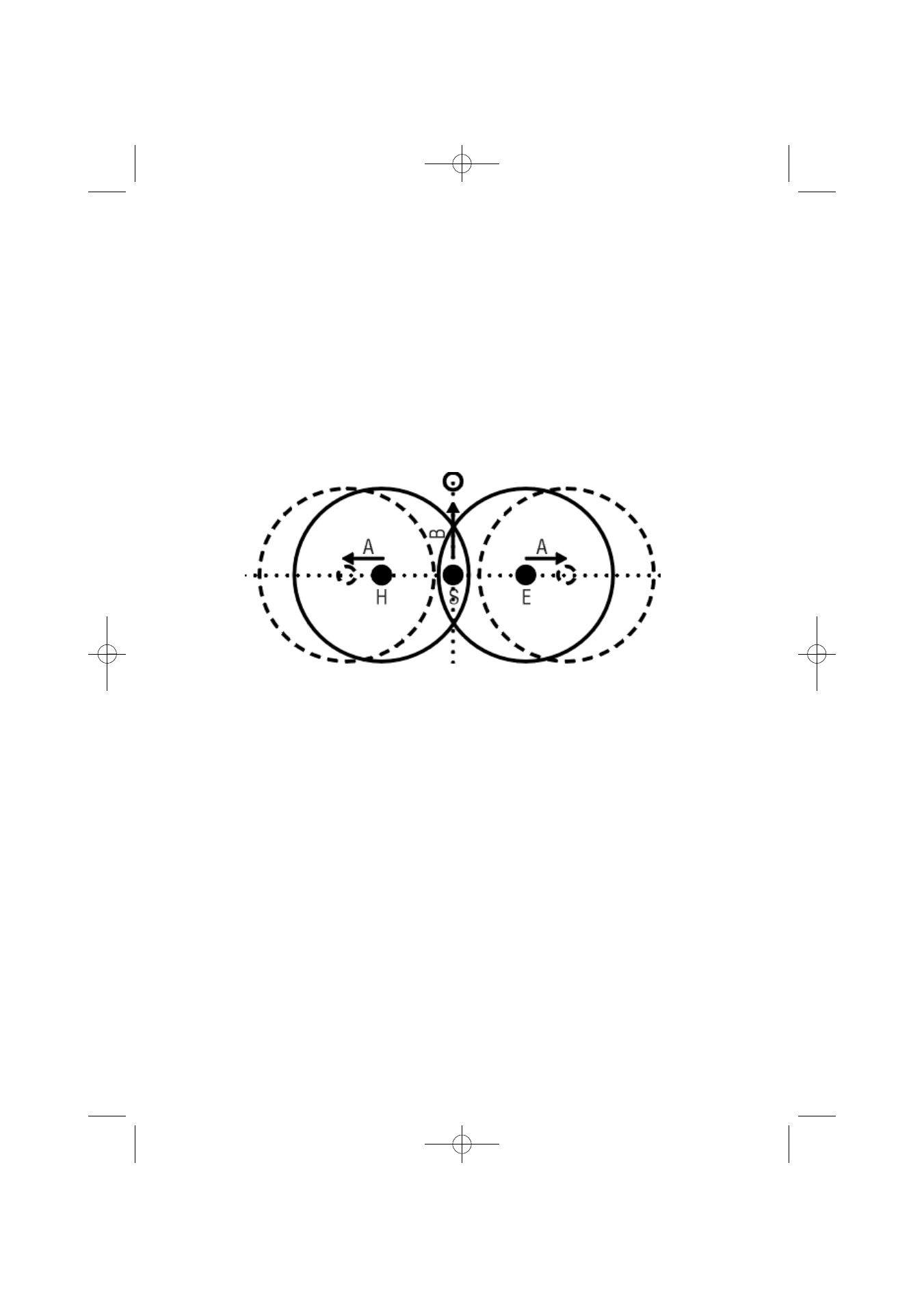
B:
position the earth rod for the probe to one point of the line outside the voltage
funnel, as shown in figure 5, and repeat the measurement.
Figure 5: Voltage funnel
• After the measurement, selection can be made between display of earth resitance (RE),
auxillary resistance (RS) and measurement current (IM) by using key “Display“ (8),
depending on the measurement result.
• The connection sequence must be respected. Otherwise the instrument will not be able to
carry out the measurement and indicates an error message:
• the display "Probe" indicates a connection error of S, E (interruptions, exchange
also with H or E)
• the "Limit IM" display indicates an interruption of the H connectors.
• Also refer to display indications
PAEB30872261:Layout 1 12.12.2007 12:06 Uhr Seite 15