Amprobe Telaris-Earth-Test Earth-Resistance-Tester User Manual
Page 20
18
• After the measurement, selection can be made between display of earth resitance (RE),
auxillary resistance (RS) and measurement current (IM) by using key “Display“ (8),
depending on the measurement result.
• The connection sequence must be respected. Otherwise the instrument will not be able to
carry out the measurement and indicates an error message:
• the display "Probe" indicates a connection error of S, E (interruptions, exchange
also with H or E)
• the "Limit IM" display indicates an interruption of the H connection.
• The procedure is carried out a different locations and at respectively varying distances "a".
Thus, the composition of the soil for the desired area is examined. Here, a measurement
at larger distances "a" gives more details about the specific earth resistance in deeper
grounds.
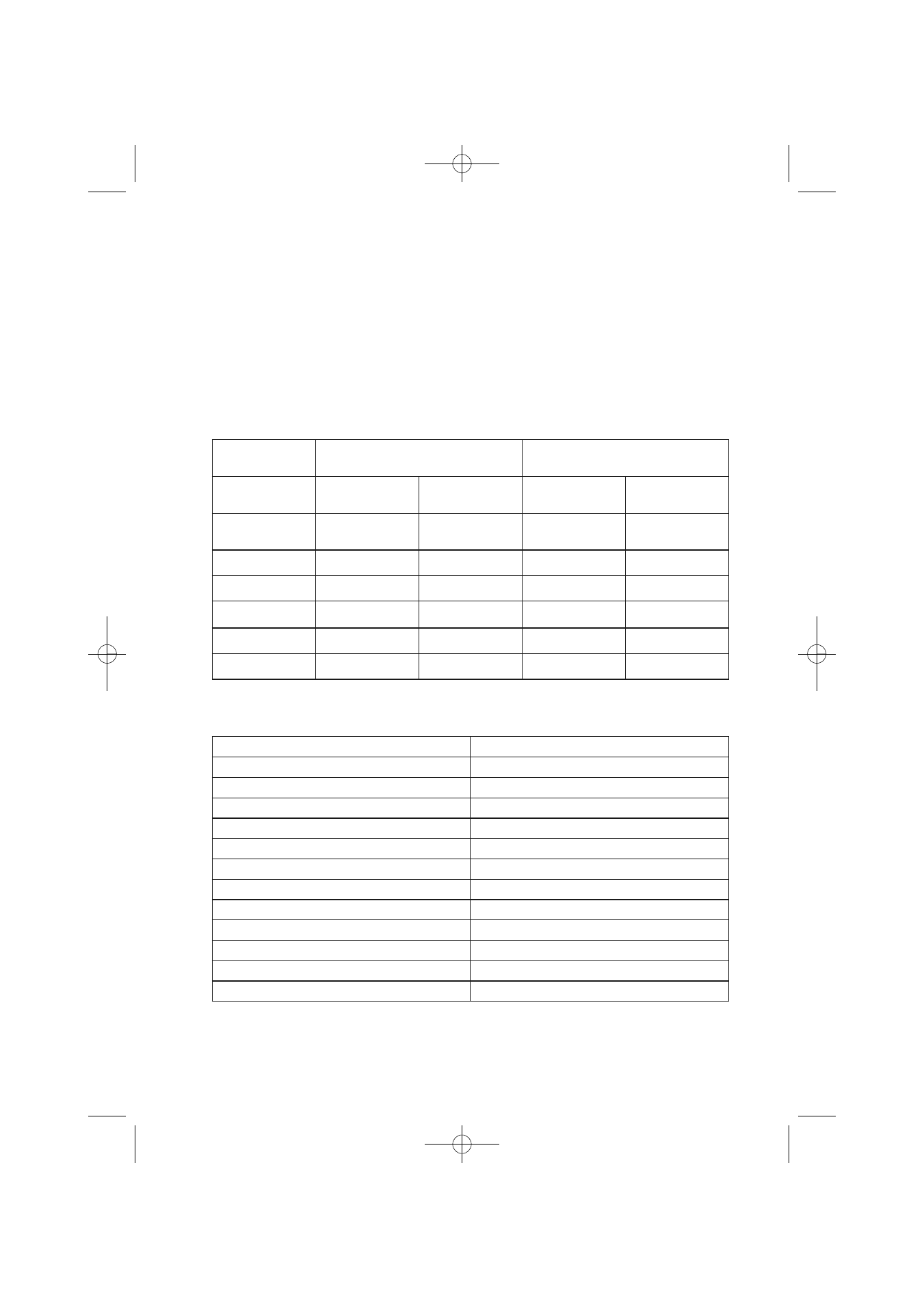
Table 1:
References to evaluate measurement results (in compliance with DIN VDE 0413
Table 2:
Example for Table 2:
Required max. permissable resistance 1
Ω.
Maximum displayed test value on EARTH-TEST 0,84
Ω.
Type of the
Ground
Earth Resistance
Bar Ground Connection
Earth Resistance
Flat Ground Connection
3m deep 5m deep
5m length 10m length
marshy
soil/swamp
10
Ω 5 Ω
12
Ω 6 Ω
arable land/clay
33
Ω 17 Ω
40
Ω 20 Ω
humid sandy soil
66
Ω 33 Ω
80
Ω 40 Ω
dry sandy soil
330
Ω 165 Ω
400
Ω 200 Ω
stony soil
1000
Ω 500 Ω
1200
Ω 60 Ω
concrete1:5
160
Ω 80 Ω
Required max. Permissable Resistance
Maximum Displayed Test Value
0.3
Ω
0.18
Ω
0.4
Ω
0.28
Ω
0.5
Ω
0.37
Ω
0.6
Ω
0.46
Ω
0.7
Ω
0.56
Ω
0.8
Ω
0.65
Ω
0.9
Ω
0.75
Ω
1.0
Ω
0.84
Ω
2. 0
Ω
1.84
Ω
3.0
Ω
2.79
Ω
4.0
Ω
3.73
Ω
5.0
Ω
4.67
Ω
PAEB30872261:Layout 1 12.12.2007 12:06 Uhr Seite 18