5 hardware connection, Internet – PLANET GSD-908HP User Manual
Page 16
16
3.5 Hardware Connection
The PoE Ethernet Switch provides flexibility to build a standard network application
or PoE network application quick and easily, simply follow the following steps:
Standard Network Application: connecting end node or switch
Step 1: Supply power to the PoE Ethernet Switch.
A. Connect one end of the power cable to the DC power adapter and
connect its DC plug connector to the PoE Ethernet Switch.
B. Connect the power plug of the power cable to a standard wall outlet.
When the PoE Ethernet Switch receives power, the Power LED should remain solid
Green.
Step 2: Connect PC or laptop to one port of the PoE Ethernet Switch using
Category 5/5e/6 UTP cabling.
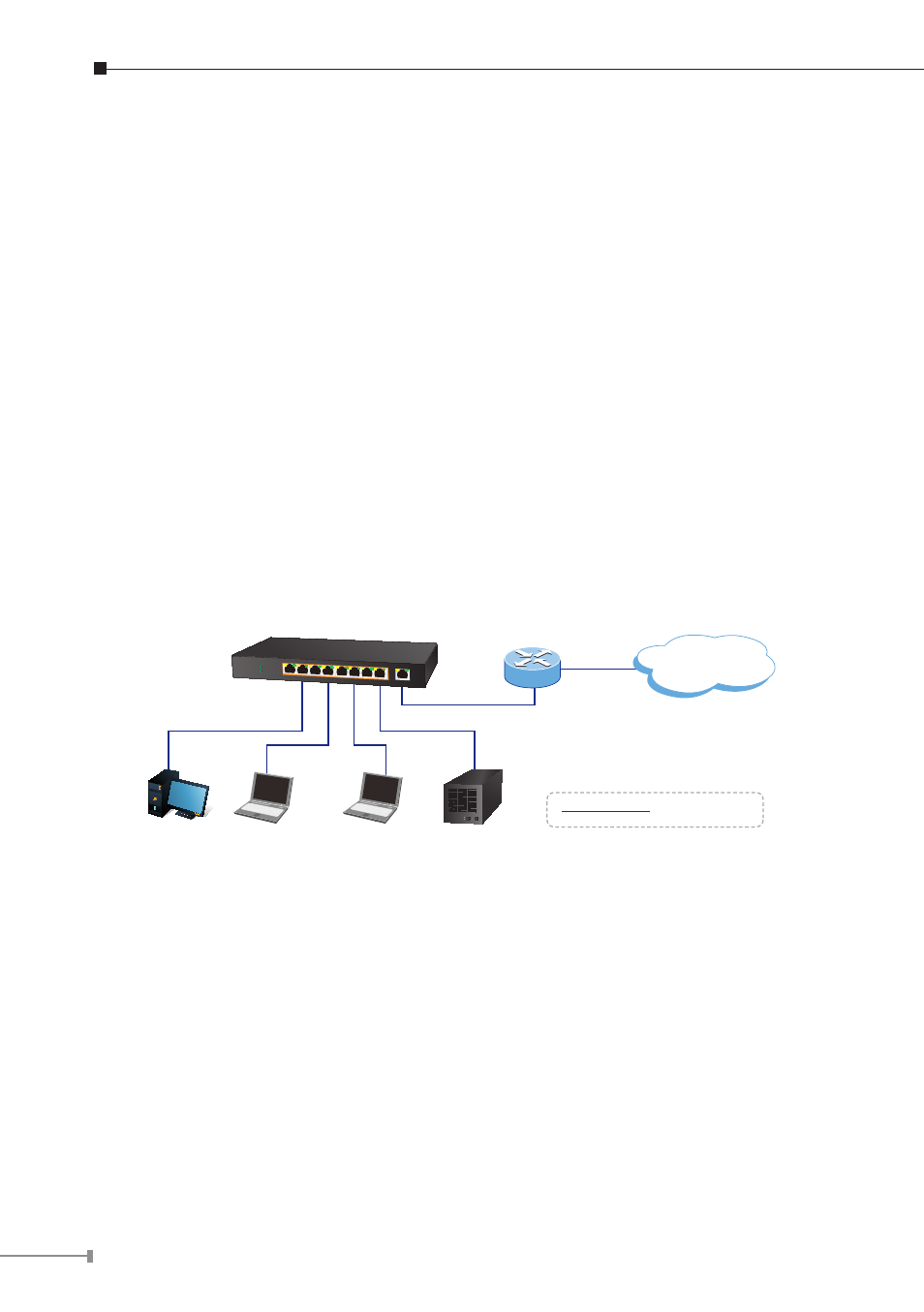
Step 3: Use an Ethernet cable to connect one upstream network devices (such as
another switch or router) to the uplink port on the switch, as shown in
Figure 3-7.
GSD-908HP
Internet
Laptop
PC
Laptop
NAS
XDSL Router
1000Base-T UTP
Figure 3-7: End Node or Switch Connection
PoE Network Application: department / workgroup PoE switch
Step 1: Supply power to the PoE Ethernet Switch.
A. Connect one end of the power cable to the DC power adapter and
connect its DC plug connector to the PoE Ethernet Switch.
B. Connect the power plug of the power cable to a standard wall outlet.
When the PoE Ethernet Switch receives power, the Power LED should remain solid
Green.