Installation instructions – PLANET LRP-101C-KIT User Manual
Page 26
26
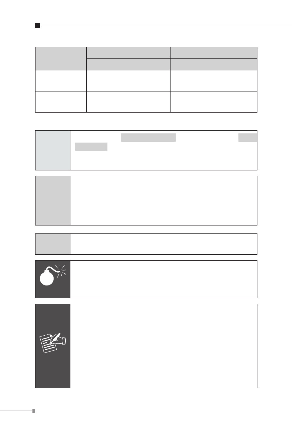
Functions
LRP Injector
LRP Extender
LRP-101CH
LRP-101CE
Power Input
RJ45 with 802.3at/af
PoE input
BNC with DC power over
coaxial input
Power
Output
BNC with DC power over
coaxial output
RJ45 with 802.3at/af
PoE output
Installation Instructions
Step 1
Connect the
LRP Injector
(LRP-101CH) and
LRP
Extender
(LRP-101CE) to ends of BNC terminated
coaxial cable.
Stick the “Warning Sticker” on the coaxial cable.
Step 2
Connect Cat5/6 UTP cable to LRP-101CH and IEEE
802.3at compliant PoE Switch or PoE Injector. If the PoE
switch or PoE injector is powered on already, then the
PWR LED of LRP-101CH and LRP-101CE should lit up
immediately.
Step 3
Connect Cat5/6 UTP cable to LRP-101CE and IEEE
802.3at/af complied PoE IP camera or PoE Wireless AP.
Warning
The LRP-101CH accepts IEEE 802.3at equipment for
optimal power injection. The other non-standard PoE
power devices may cause the LRP-101CH to malfunction.
Note
1. Before installation, please consider the distance
and watts value demand for PD devices. The LRP-
101C-KIT PoE powers output capacity and upload /
download performance depending on the length of
coaxial cable.
2. As there are various resistance values in the category
of RG-59/U or RG-6/U cable, the actual data rate will
vary on the quality of the copper wire and environ-
mental factors.