3 ica-hm830w installation – PLANET ICA-HM830W User Manual
Page 11
11
Terminal block for I/O connectors:
Name
Pin
Function
GND
1
Four sets of Digital Input, DI1 until DI4; the internal
device is also photo-coupled electrical relay. In practice,
the external device can be simply an On/Off switch.
Four sets of On/Off switch can be connected as different
trigger source.
Digital input 4
2
Digital input 3
3
Digital input 2
4
Digital input 1
5
DO_NO
6
Digital output implementation; Pin6 to COM (Pin7) is a
Photo-coupled relay on Normal Open status. External
device can directly connect to the terminals. However
the current that will go through the 2 nodes must
not exceed 130mA. An external “Relay” can also be
connected to the terminals as an implementation. In this
case, current (or/and voltage) limitation is specified by
the external Relay.
DO_COM
7
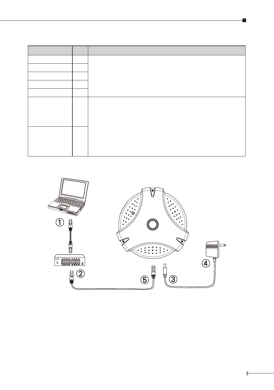
2.2.3 ICA-HM830W Installation