ProSoft Technology MVI69-ADM User Manual
Page 38
Understanding the MVI-ADM API
MVI-ADM ♦ 'C' Programmable
Developer's Guide
'C' Programmable Application Development Module
Page 38 of 342
ProSoft Technology, Inc.
February 20, 2013
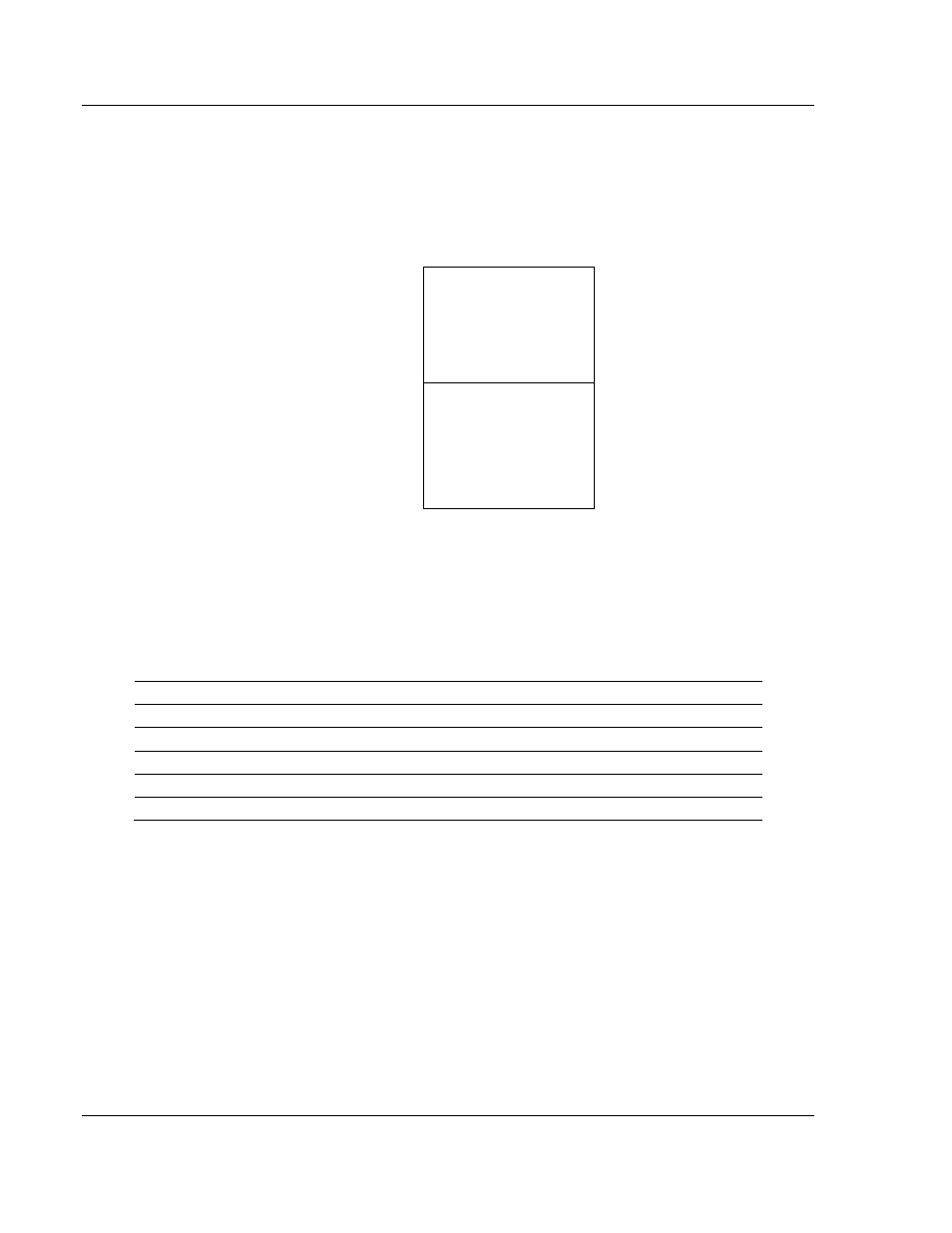
All data transferred between the module and the processor over the backplane is
through the input and output images. Ladder logic must be written in the
CompactLogix processor to interface the input and output image data with data
defined in the Controller Tags. All data used by the module is stored in its internal
database. The following illustration shows the layout of the database:
Module’s Internal Database Structure
5000 registers for user data
0
Register Data
4999
3000 words of configuration and
status data
5000
Status and Config
7999
Data contained in this database is paged through the input and output images by
coordination of the CompactLogix ladder logic and the MVI69-ADM module's
program. Up to 242 words of data can be transferred from the module to the
processor at a time. Up to 241 words of data can be transferred from the
processor to the module. The read and write block identification codes in each
data block determine the function to be performed or the content of the data
block. The block identification codes used by the module are listed below:
Block Range
Descriptions
-1
Status Block
0
Status Block
1 to 999
Read or write data
9998
Warm-boot control block
9999
Cold-boot control block
Each image has a defined structure depending on the data content and the
function of the data transfer.
Normal Data Transfer
Normal data transfer includes the paging of the user data found in the module’s
internal database in registers 0 to 4999 and the status data. These data are
transferred through read (input image) and write (output image) blocks. The
structure and function of each block is discussed in the following topics: