JVC GY-HC900STU 2/3" HD Connected Cam Studio Camcorder (Body Only) User Manual
Page 70
When the switch setting is set to “FRONT”
Audio recording is performed according to the
setting in [A/V Set]
B
[Audio Set]
B
[Front Mic
Select]/[Front Mic Power]/[Front Mic 1 Ref.]/[Front
Mic 2 Ref.].
Caution :
0
Set [Front Mic Select] to “Stereo M/S” to convert
the audio signal to stereo (L/R) signal for
recording when a Mid/Side direct output
microphone is connected.
Do not set to “Stereo L/R” or “Mono” when an L/
R out stereo microphone or a monophonic
microphone is connected.
When the switch setting is set to “REAR”
Select the audio input to the [AUDIO INPUT 1/2]
terminal using the [AUDIO INPUT 1/2] switch.
Setting
Description
[LINE]
Use this setting when connecting to
an audio device or other equipment.
[MIC]
Use this setting when connecting to
a dynamic microphone.
[MIC+48V] Use this setting when connecting to
a microphone (phantom
microphone) that requires a +48 V
power supply.
Memo :
0
When “LINE” is selected, configure the
reference input level in [A/V Set]
B
[Audio Set]
B
[Rear Line Ref.].
0
When “MIC” or “MIC+48V” is selected, set the
reference input level in [A/V Set]
B
[Audio Set]
B
[Rear Mic 1 Ref.]/[Rear Mic 2 Ref.].
Caution :
0
When connecting a device that does not require
a +48 V power supply, make sure that it is not
set to the “MIC+48V” position.
0
When the [AUDIO INPUT 1/2] switch is set to
“MIC”, make sure that a microphone is
connected to the [AUDIO INPUT 1/2] terminal. If
you increase the recording level when a
microphone is not connected, noise from the
input terminal may be recorded.
0
When a microphone is not connected to the
[AUDIO INPUT 1/2] terminal, set the [AUDIO
INPUT 1/2] switch to “LINE”.
When the switch setting is set to “WIRELESS”
Recording is performed as follows according to the
setting in [A/V Set]
B
[Audio Set]
B
[Wireless
Channel].
“UniSlot”
Wireless
Receiver
Camera
Single:
CH1
B
CH1/CH2
Dual:
CH1
B
CH1
CH2
B
CH2
Caution :
0
Power is supplied to the “UniSlot” wireless
receiver when any of the CH1/CH2/CH3/CH4
switches is set to “WIRELESS”.
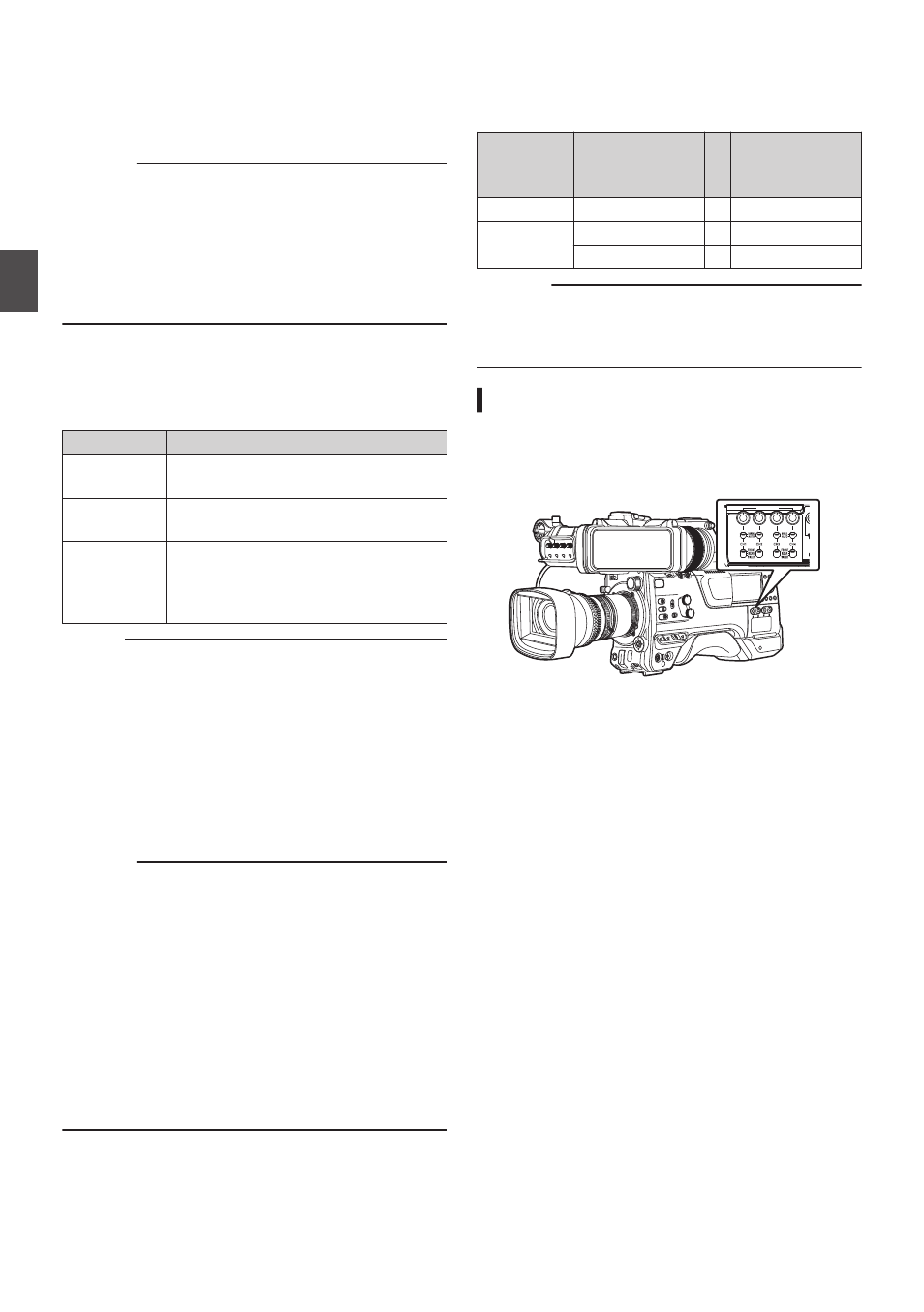
Adjusting the Audio Recording Level
You can select to adjust the audio recording levels
for each of the four channels (CH1/CH2/CH3/CH4)
manually or automatically.
.
PR
AUDIO INPUT
DIS
70
Audio Recording
Sh
ooting