Altera RAM-Based Shift Register User Manual
Page 17
Chapter 2: Getting Started
2–11
Design Example: Shift Register with Taps
May 2013
Altera Corporation
RAM-Based Shift Register (ALTSHIFT_TAPS) Megafunction User Guide
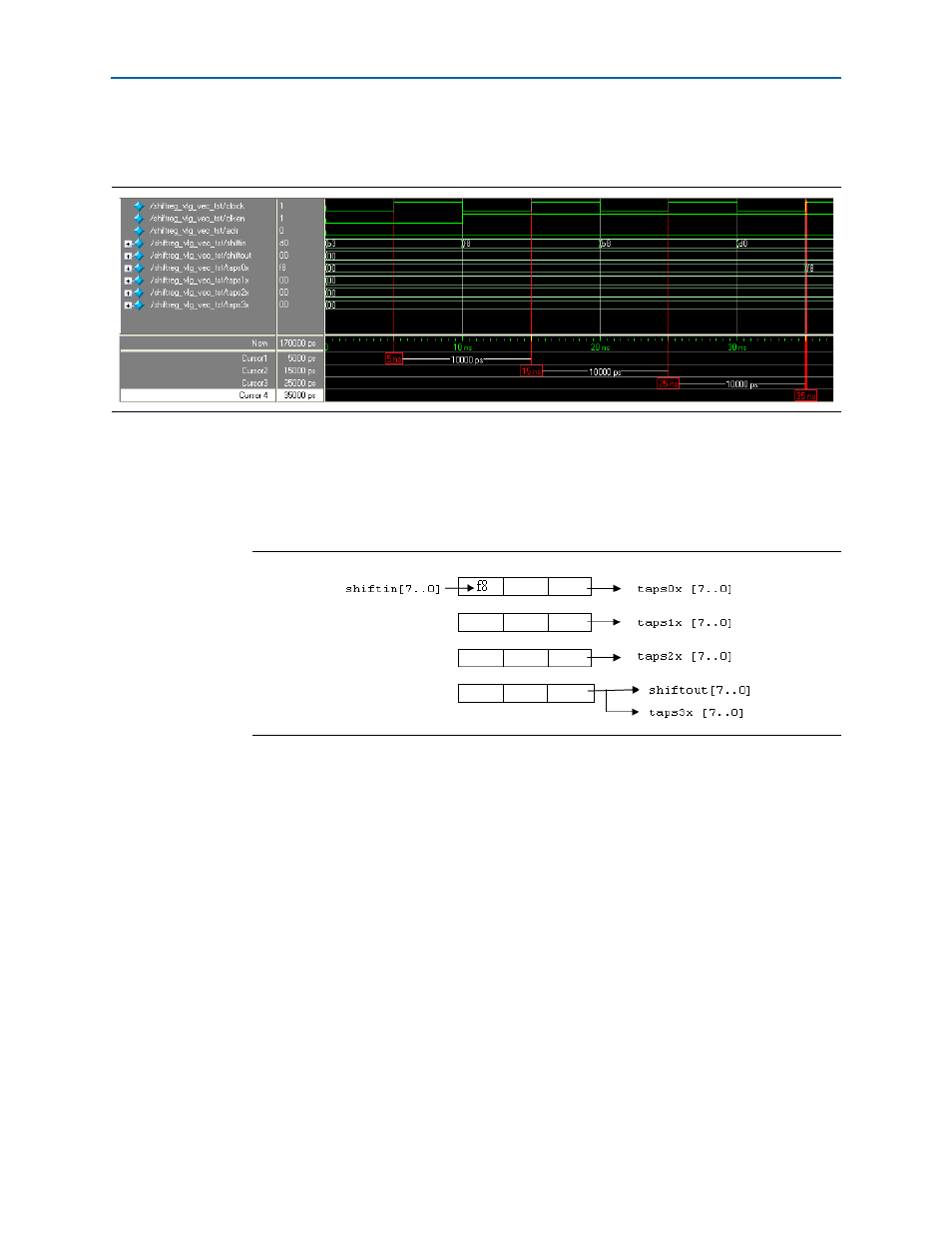
shows the first three data words written into the shift register chain, shifted
in the register chain, and the first data shown at the taps0x output.
At 5 ns, the clken signal is low and therefore no operation is executed. You can
consider 15 ns to be the first rising clock edge, as this is when the operation begins.
The first data F8 is shifted into the shift register as shown in
. All outputs
show 00 because no data is being shifted to any of the outputs.
At 25 ns and 35 ns, the second data B8 and the third data D0 are shifted into the shift
register, respectively.
1
The existing data in the shift register chain are shifted right before the shift-in of new
data.
shows the content in the shift register chain at 35 ns. All of the outputs
show 00 except taps0x, which shows the first data, F8.
Figure 2–9. First Three Data Written and Shifted in the Shift Register
Figure 2–10. Content of the Shift Register Chain at 15 ns