General information, General information –22 – Altera DSP Development Kit, Stratix V Edition User Manual
Page 46
6–22
Chapter 6: Board Test System
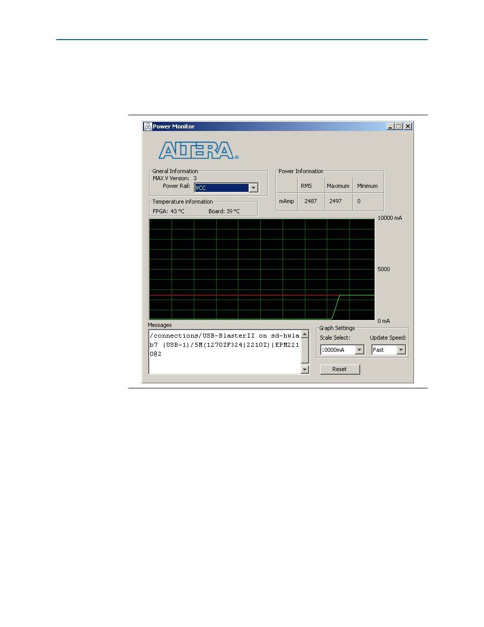
The Power Monitor
DSP Development Kit, Stratix V Edition
July 2013
Altera Corporation
User Guide
The Power Monitor communicates with the MAX V device on the board through the
JTAG bus. A power monitor circuit attached to the MAX V device allows you to
measure the power that the Stratix V GS FPGA device is consuming regardless of the
design currently running.
shows the Power Monitor.
The following sections describe the Power Monitor controls.
General Information
The General information controls display the following information about the
MAX V device:
■
MAX V version
—Indicates the version of MAX V code currently running on the
board. The MAX V code resides in the <install
dir>\kits\stratixVGS_5sgsmd5kf40_dsp\factory_recovery and <install
dir>\kits\stratixVGS_5sgsmd5kf40_dsp\examples\max5 directories. Newer
revisions of this code might be available on the
ge of the Altera website.
■
Power rail
—Selects the power rail to measure. After setting the Power rail list to
the desired rail, click Reset to refresh the screen with new board readings.
1
All rails use a 0.003 ohm resistor, except S5_VCCINT that uses 0.001 ohms.
Figure 6–10. The Power Monitor