The gpio fpga1 tab, User dip switches, User leds – Altera Stratix V Advanced Systems User Manual
Page 23: The gpio fpga1 tab –5, User dip switches –5 user leds –5
Chapter 5: Board Test System
5–5
Using the Board Test System
February 2013
Altera Corporation
Stratix V Advanced Systems Development Kit
User Guide
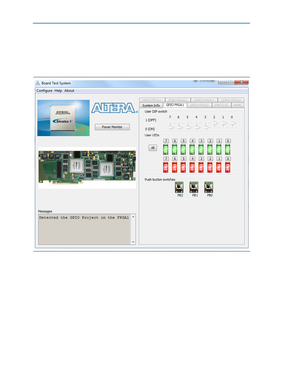
The GPIO FPGA1 Tab
The GPIO FPGA1 tab allows you to interact with all the general purpose user I/O
components on your board associated with FPGA1 (U29). You can read DIP switch
settings, turn LEDs on or off, and detect push button presses. This test erases FPGA2.
shows the GPIO FPGA1 tab.
The following sections describe the controls on the GPIO FPGA1 tab.
User DIP Switches
The read-only User DIP switch control displays the current positions of the switches
in the user DIP switch bank (SW1). Change the switches on the board to see the
graphical display change accordingly.
User LEDs
The User LEDs control displays the current state of the user LEDs. To toggle the board
LEDs, click the 0 to 7 buttons to toggle red or green LEDs, the All button, and the
graphical representation of the LEDs.
Figure 5–3. The GPIO FPGA1 Tab