CIRCUTOR CBS8 (Available until stocks) User Manual
Page 9
----- Relay Station CBS-8 -------- --- Page No. 8
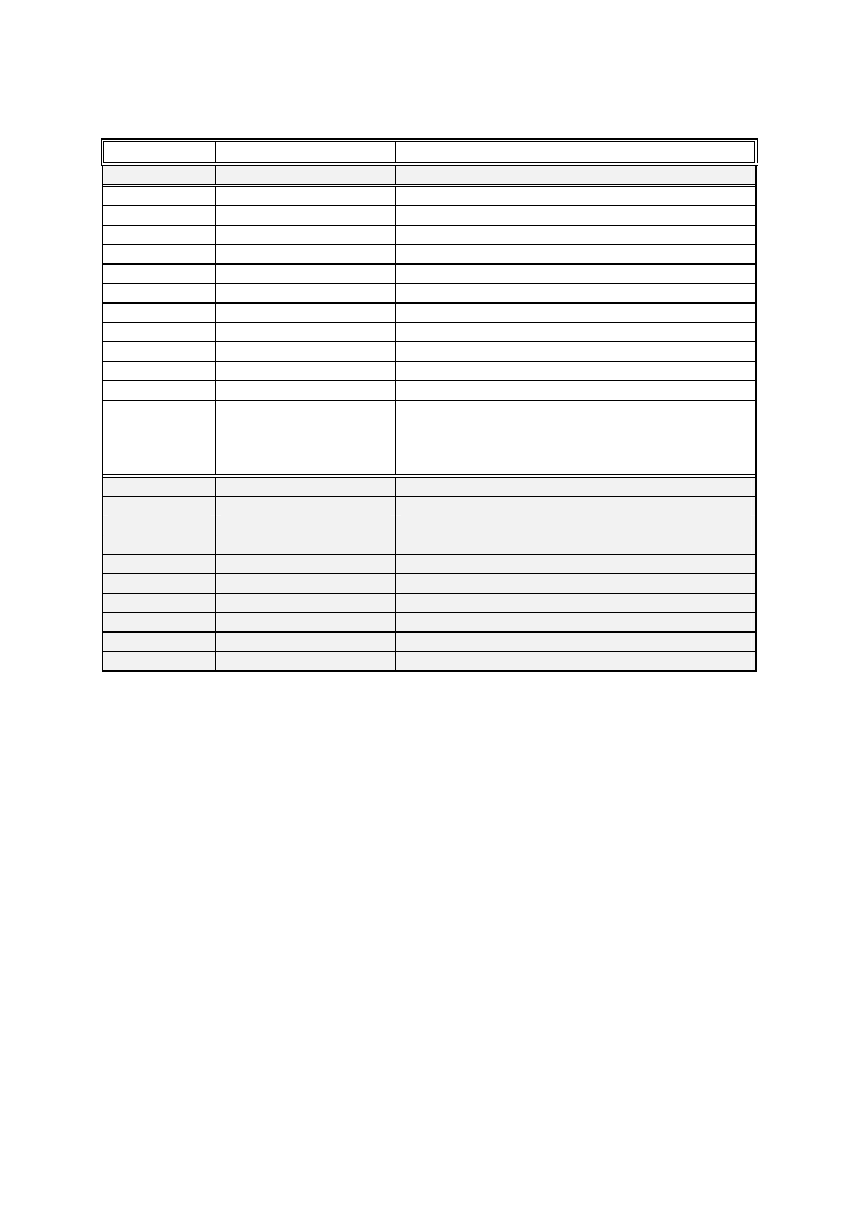
3.2.- CBS-8 terminal ratios (as labels)
Terminal No
Name
Type
1 - 28
Power Supply A1 - A2 Power supply 230 V AC.
27 – 26
Test 1 - Test 2
Test output
25
COM
Common relay outputs
24
RL1
Relay output channel 1
23
RL2
Relay output channel 2
22
RL3
Relay output channel 3
21
RL4
Relay output channel 4
20
RL5
Relay output channel 5
19
RL6
Relay output channel 6
18
RL7
Relay output channel 7
17
RL8
Relay output channel 8
16 - 15
ALARM
Alarm output
14
13
12
GND
( -- )
(+ )
COM CBS-8: RS-485 connection to PC.
14 GND ---------> 5 converter
13 -- ---------> 2 (--) RS-485/RS-232
12 + ---------> 1 (+)
11
T8 – S1
S1 Current transformer channel 8
10
T7 –S1
S1 Current transformer channel 7
9
common – S2
S2 Current transformer channels 5,6,7 and 8
8
T6–S1
S1 Current transformer channel 6
7
T5–S1
S1 Current transformer channel 5
6
T4–S1
S1 Current transformer channel 4
5
T3–S1
S1 Current transformer channel 3
4
common-S2
S2 Current transformer channels 1,2,3 and 4
3
T2–S1
S1 Current transformer channel 2
2
T1–S1
S1 Current transformer channel 1
NOTE: Current inputs are designed for WG or WGP transformers.