Dmx terminations – Tempest Thunder User Manual
Page 31
Thunder Enclosure User Manual
page
31
When you switch power ON to the DEC3.3 controller (firmware 01.00.006 and up), the following
indications will confirm that the major system elements are working correctly:
BEEP! – a loud beep indicates that the processor has initialized and is functioning
correctly.
FANS – fans run for three seconds
HEATER – the heater turns on for 15 seconds. This is enough to get warm to the touch.
DMX Connections
DMX refers to USITT DMX512, a commonly used control protocol in the entertainment industry,
running over RS485. Consult USITT DMX installation guidelines when laying out a system, or
employ a qualified DMX system integrator.
A DMX network will be required if:
a) The luminaire inside the enclosure requires a DMX control signal
b) You wish to monitor the enclosure using RDM
c) You wish to control the enclosure lamp relay over DMX
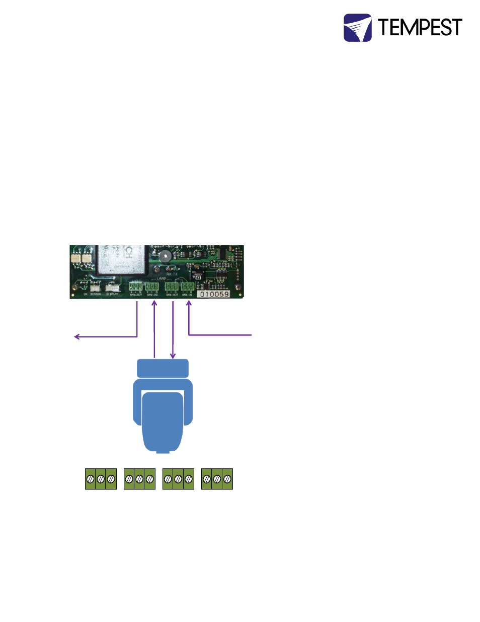
DMX Terminations
Note: DMX will not normally be used in
luminaire installations.
Pinout: (1) Ground, (2) Data -, (3) Data
+.
DMX Connectors:
1 DMX IN from network
2 DMX OUT to luminaire (or to
network if not controlling luminaire)
3 DMX IN from luminaire
4 DMX OUT to network
Note: If the enclosed equipment does
not use DMX, then connector (2) on the
controller is DMX OUT for the enclosure.
DMX Line Terminations
DMX cable runs must be terminated at
the far end of the cable run with a termination
resistor as detailed in the DMX512 standard.
The individual equipment installed inside the
Tempest enclosures must NOT be terminated.
It is recommended that any line termination is done using the 3-pin terminal connector fitted to
the DEC3.3 control circuit board.
DMX IN from
outside world
DMX OUT to
next DMX device
❹ ❸ ❷
❶
+ ‒ G
DMX OUT
+ ‒ G
DMX OUT
LIGHT
+ ‒ G
DMX IN
LIGHT
+ ‒ G
DMX IN
DMX terminal Pinout Detail