Rear panel connectors and outputs, Figure 1.3 rear panel, Figure 1.2 – AMETEK XT Series User Manual
Page 16
Advertising
Features and Specifications
Rear Panel Connectors and Outputs
14
Operating Manual for XT Series Power Supply
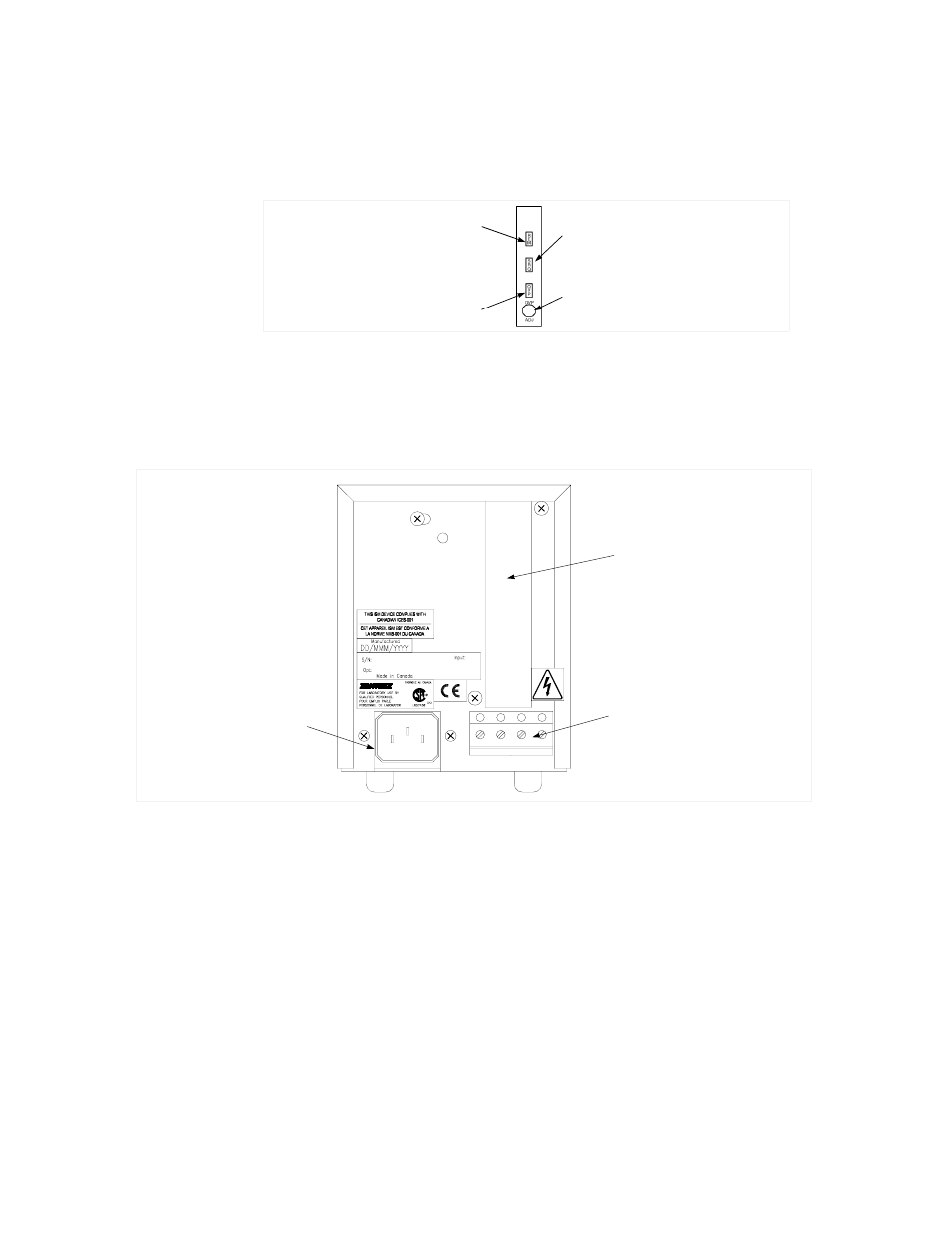
Figure 1.2 Remote Programming Interface Indicators (For units with a digital
programming interface installed.)
Rear Panel Connectors and Outputs
for the connectors and outputs available at the rear panel.
Figure 1.3 Rear Panel.
Remote Programming LED (REM)
Shutdown LED (SRQ)
OVP Shutdown (OVP)
OVP Adjust Potentiometer (OVP ADJ)
AC Input Connector
Blank Subplate
(Replaced if a
programming option
is installed.)
Output Terminal Block
Advertising