AMETEK XT Series User Manual
Page 36
Operation
Using Multiple Supplies
36
Operating Manual for XT Series Power Supply
Connecting
Multiple
Supplies in
Parallel
Connect power supplies in parallel to obtain a single output supply with a higher
output current limit. Set all of the outputs to the same voltage before connecting the
positive (+) and negative (
−) terminals in parallel. The total current available is the
sum of the maximum currents of each supply.
The maximum voltage available at the load is equal to the voltage of the lowest rated
supply. When you connect two supplies in parallel, the supply with the higher
voltage setting will be in the current limiting mode, while the other supply controls
the output voltage
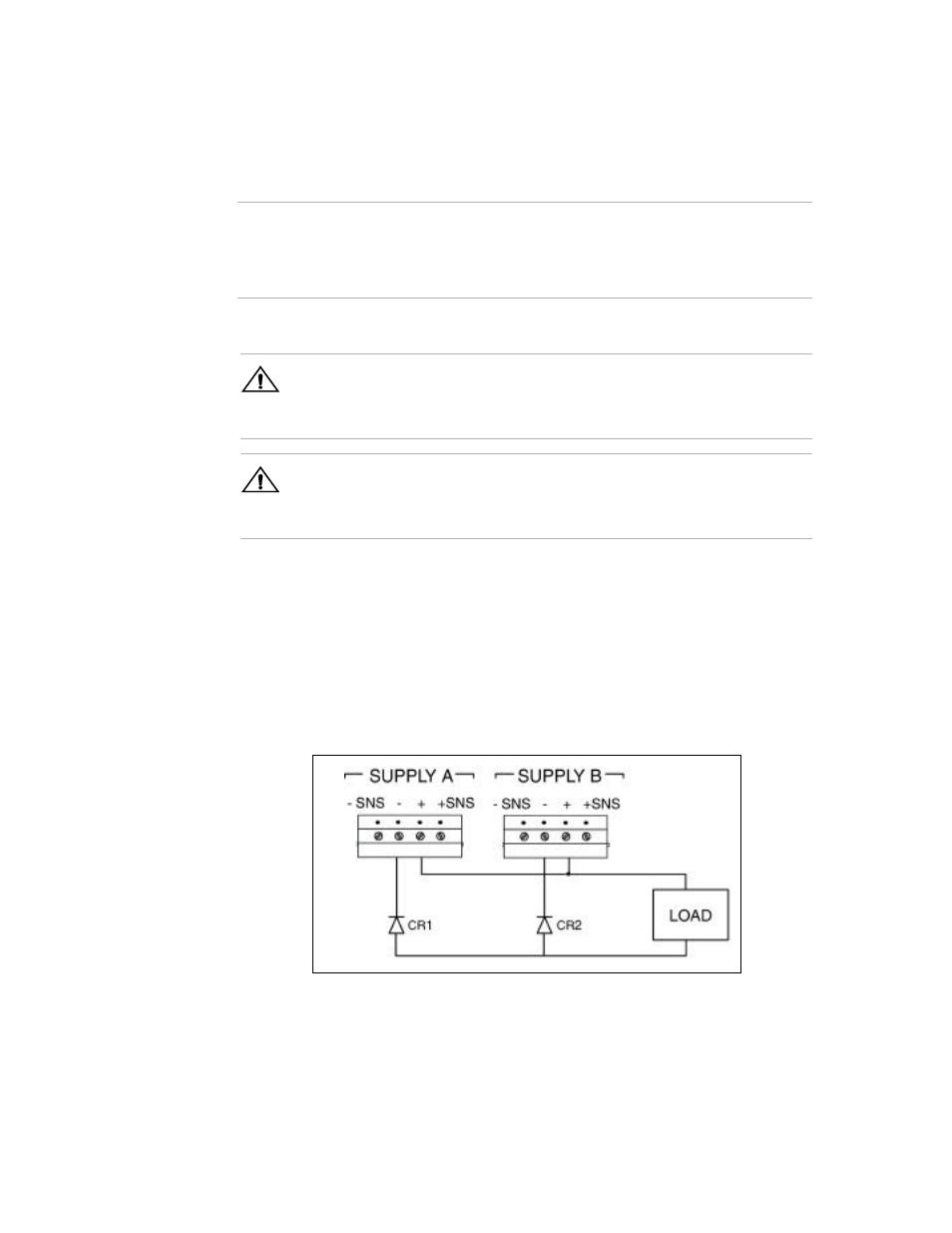
Figure 4.3 Parallel Operation with OVP-equipped Units
(Local Sensing Only)
Note
You do not need to use remote sensing for series operation. If you choose to use it,
refer to
“Remote Sensing” on page 32
.
Diodes CR1 and CR2 protect sense circuits during transient events such as
momentary current limit events which may cause supply outputs to collapse.
!
CAUTION
For parallel operation with OVP-equipped supplies, set all OVP trip points higher
than the maximum output voltage. To prevent the internal OVP fuse from blowing
during OVP trip events, add external blocking diodes as illustrated in Figure 4.3.
!
CAUTION
The configuration shown in Figure 4.3 is for use with local sense only. Do not
attempt to use remote sensing with the diodes as shown. Damage to the sense
circuits may occur.