Wiring diagram, Replacement parts, Maintenance – Avalon Firestyles Salish-1999 to 2000 User Manual
Page 25: 120 v. blower circuit
Maintenance
25
Travis Industries
9 3 5 0 8 1 0 7
1 0 0 2 0 1
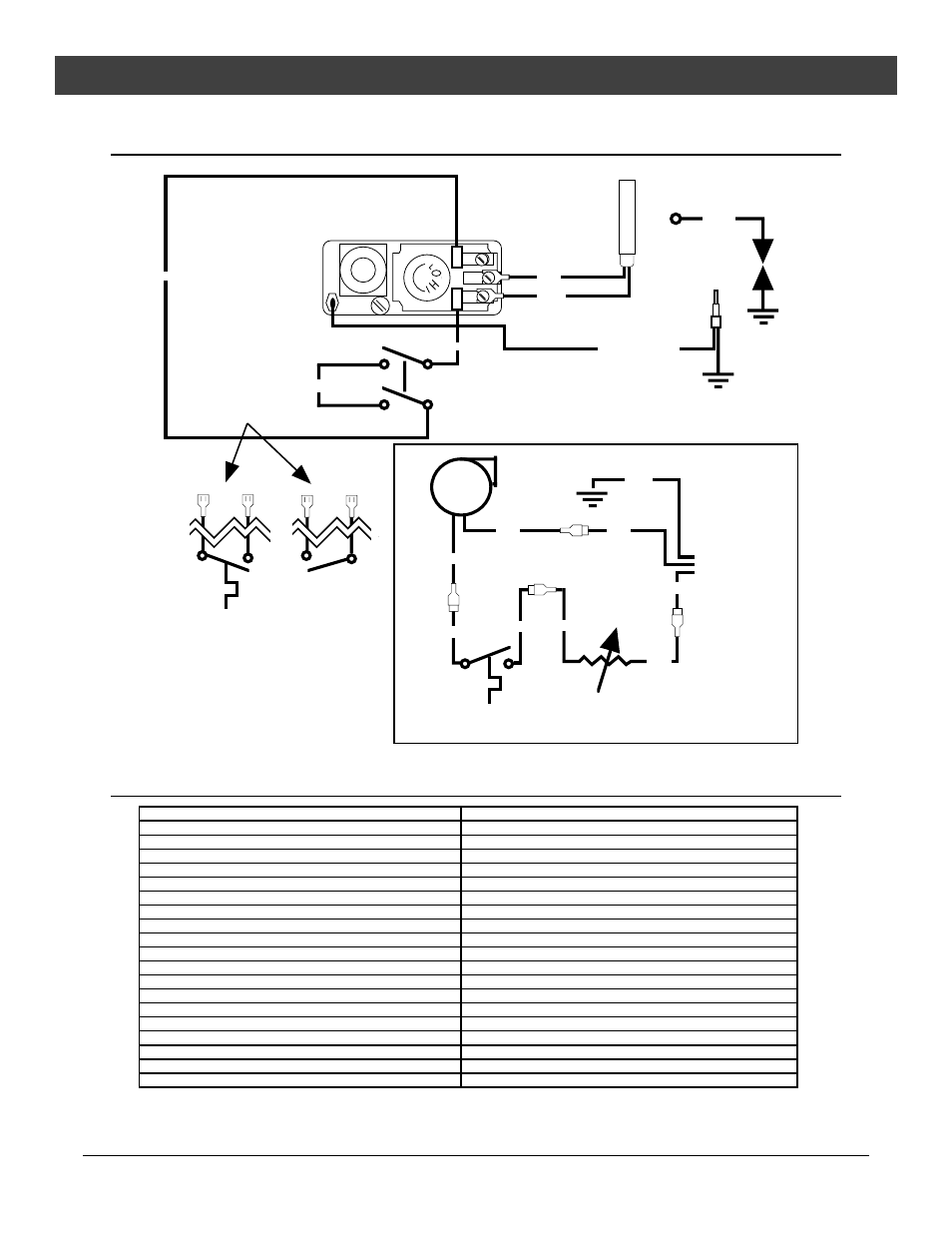
Wiring Diagram
Jumper Wire
(Manual
Operation)
Piezo Igniter
Orange
On/Off
Switch
Thermopile
Red
Brown
EPU
terminal
White
Red
Thermocouple
Green
120 Volt
Grounded A.C.
Power Supply
Blower
Rheostat
Blower
Motor
Chassis
Ground
Black
Blower
Thermodisk
Green
White
White
Black
Black
Black
Black
120 V.
Blower
Circuit
Gas Control Valve
Optional
Remote
Control
Optional
Thermostat
Copper Co-Axial Wire
White
Replacement Parts:
Blower, Convection
93006080
Orifice, Pilot, .021
91001505
Blower Rheostat w/ Off Position
98900758
Piezo Igniter
98900751
Brick Floor Plate
93006071
Pilot Assembly, LP
93006021
Burner Tube
93006000
Pilot Assembly, NG
93006020
Control Valve, LP
97300130
Pilot Tube
91001508
Control Valve, NG
97300120
Power Cord, With Molex Connector
99300656
Conversion Parts, LP
93006030
Pressure Relief Doors
91001541
Conversion Parts, NG
93006031
Regulator, Natural Gas
98900733
Door Gasketing
99900402
Regulator, Propane (LP)
98900734
Glass Gasket, Flat Fiberglass Tape
99900404
Snap Disk
98900720
Glass, Front
Switch, On/Off
98900747
Glass, Side
Thermocouple
98900748
Glowing Ember Strip
93006052
Thermopile
98900752
Knob, for Rheostat
99300657
Thermostat, Remote
99300653
Log, Ember Coals
99300114
Thermostat, Wall Mounted
99300650
Log Set, Large ( One Piece)
93006050
Wiring Harness
97200307
Manual
93508107
Orifice, Gas, .125Ó , NG
93006011
Orifice, Gas #48, LP
93006010
Orifice, Pilot, .016
91001506