Vent configurations, Restrictor, Installation – Avalon Firestyles Salish-1999 to 2000 User Manual
Page 9: Approved vent configurations, For qualified installers only), Restrictor position, Elbows, Measuring vent lengths
Installation
(for qualified installers only)
9
Travis Industries
9 3 5 0 8 1 0 7
1 0 0 2 0 1
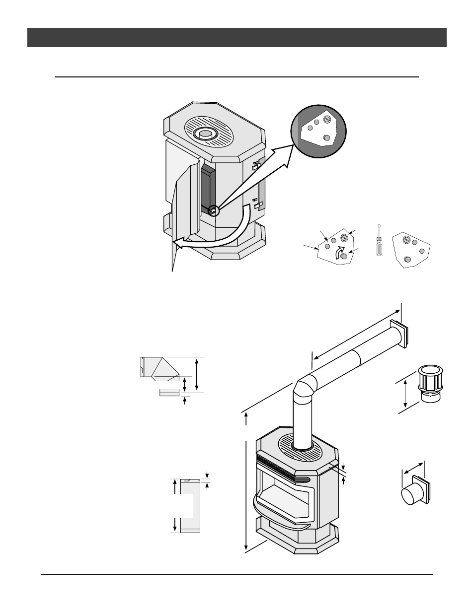
Approved Vent Configurations
Restrictor Position
¥
A vent restrictor is built
into the appliance to
control the flow rate of
exhaust gases. This
ensures proper flames
for the wide variety of
vent configurations. The
restrictor consists of a
butterfly valve in the air
inlet and an adjustment
plate with index holes
used to hold the valve in
a fixed position.
Depending upon the
vent configuration, you
may be required to adjust
the restrictor position.
The charts for approved
vent configurations
describe which position
the vent restrictor must
be in.
To Adjust the Restrictor:
1
2
3
4
The three holes on the
restrictor plate
correspond to the three
restrictor positions.
Determine the correct restrictor position (see the
charts under "Approved Vent Configurations" - the stock
position is #1). Swing the left access panel open.
Remove the screw with a 1/4" nutdriver (or screwdriver).
Rotate the adjustment plate clockwise until the correct
index hole is above the pivot point.
Insert the screw into the correct index hole and tighten.
NOTE:
Position #1 is the fully open position
1/4" Nutdriver
Adjustment
Plate
Index Holes
Pivot
Point
Screw
1
2
3
This restrictor is
in Position #3.
Elbows
¥
2 Elbow
maximum
(two 45¡ or
two 90¡, not one
45¡ and one 90¡)
Measuring
Vent Lengths
Vent Horizontal Run
(measure from the closest
edge of the starter section to
the end of the termination)
Vent Height is
calculated to the
top of the vent on
horizontal
terminations and
to the top of the
termination on
vertical
terminations.
Vent
Height
Elbows add 3" (75 mm) to the
length of the vent system.
Side
View
9-5/8"
(245 mm)
Vent Length
(3', 4', etc.)
(910, 1210 mm)
Vent sections overlap each
other by 1-1/2" (37 mm)
8-3/4" (220 mm) wide
with 1-1/2" (37 mm)
to 3-3/8" (85 mm) of
overlap
The starter
section is
1/4"" above
the top
12-3/8" (310 mm) tall
with 1-1/2" (37 mm)
of overlap
3" (75 mm)
1-1/2" (37 mm)
1-1/2"
(37 mm)