Introduction, Function block descriptions, Current sensing input – Basler Electric BE1-50/51B-235 User Manual
Page 27: Power ct and power supply, Signal conditioning, Microprocessor, Section 3 • functional description -1, Introduction -1, Function block descriptions -1, Current sensing input -1
9252000898 Rev B
BE1-50/51B-235/-236 Functional Description
3-1
SECTION 3 • FUNCTIONAL DESCRIPTION
INTRODUCTION
This section illustrates and describes the functional capabilities of the BE1-50/51B-235 and BE1-50/51B-
236 relays.
FUNCTION BLOCK DESCRIPTIONS
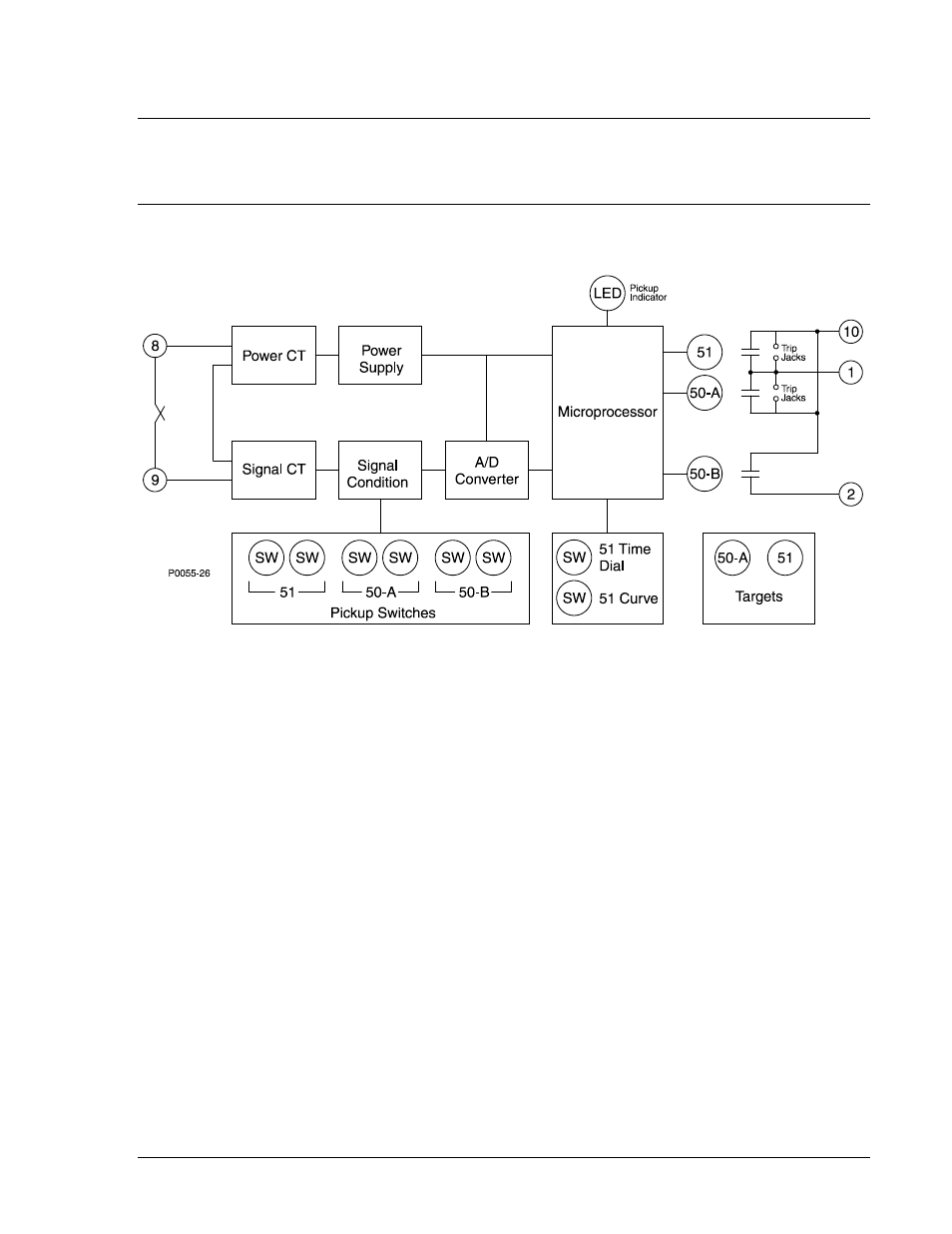
The function blocks of the BE1-50/51B-235 and BE1-50/51B-236 relays are illustrated in Figure 3-1 and
described in the following paragraphs.
Figure 3-1. Function Block Diagram
Current Sensing Input
Single-phase ac current supplied by a system current transformer (CT) is applied to the BE1-50/51B-235
and BE1-50/51B-236 through terminals 8 and 9. Sensing current is applied to internal power and signal
CTs.
Power CT and Power Supply
The output of the power CT is supplied to the power supply which provides rectified and filtered operating
power for all relay circuitry. A precision 5 Vdc output of the power supply serves as a reference for
automatic calibration.
Signal Conditioning
Current from the signal CT is rectified and applied to three independent sets of scaling resistors controlled
by the Time Overcurrent (51), Instantaneous Overcurrent A (50-A), and Instantaneous Overcurrent B (50-
B) pickup switches. The analog-to-digital converter receives the analog voltage developed across the
scaling resistors and converts it into a digital signal that is supplied to the microprocessor.
Microprocessor
The microprocessor performs program operations based on the sensed current, switch settings, and the
internal software program.
When sufficient current is sensed by the relay, the microprocessor is active and executing code, and the
Active/Pickup LED is green. When the sensed current decreases below the operating threshold,
microprocessor operation is interrupted and the Active/Pickup LED turns off. A watchdog circuit resets the
microprocessor program when code execution is interrupted.