Manual trip, Manual trip -10, Figure 5-6. target indicator test setup – Basler Electric BE1-50/51B-235 User Manual
Page 46
5-10
BE1-50/51B-235/-236 Testing
9252000898 Rev A
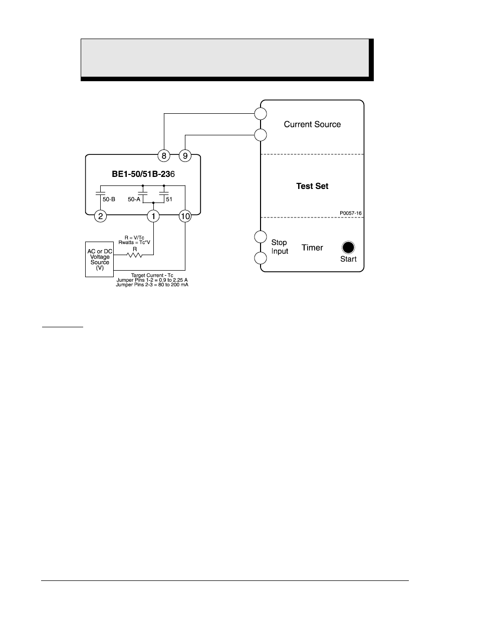
Figure 5-6. Target Indicator Test Setup
1. Configure the relay for manual trip testing:
Manual Trip
a. Connect the test setup as shown in Figure 5-4.
b. Set circuit board switch SW3 as follows:
SW3-1 = ON for 50 Hz operation or OFF for 60 Hz operation
SW3-2 = OFF (no additional time delay for the 50-A element)
SW3-3 = ON (Westinghouse CO type characteristic curves)
SW3-4 = ON (integrating reset characteristic)
c. Set TIME DIAL to 0.0
d. Set CURVE to S.
e. Set TIME PICKUP to 0.2.
f. Set INST PICKUP (50-A) to 18.0.
g. Set INST PICKUP (50-B) (accessed at the top side of the assembly) at 20 (0.4 Aac).
2. Apply 0.18 Aac to terminals 8 and 9 (0.18 Aac provides relay operating power but is below the pickup
threshold.)
3. Connect a jumper to the Time Overcurrent Manual Trip jacks. Verify that the stop input of the test set
timer recognizes a 51 contact closure.
4. Remove the jumper and the current applied at relay terminals 8 and 9.
5. Apply 0.18 Aac to terminals 8 and 9.
6. Connect a jumper to the Instantaneous Overcurrent Manual Trip jacks. Verify that the stop input of
the test set timer recognizes a 50-A contact closure
7. Remove the jumper and the current applied to relay terminals 8 and 9.
8. Reset targets.
WARNING!
Trip circuit voltage is present at the front panel test points. When shorting the test
points, use insulated jumpers to avoid contact with these voltages.