Cybex 625C Cycle Bike User Manual
Page 24
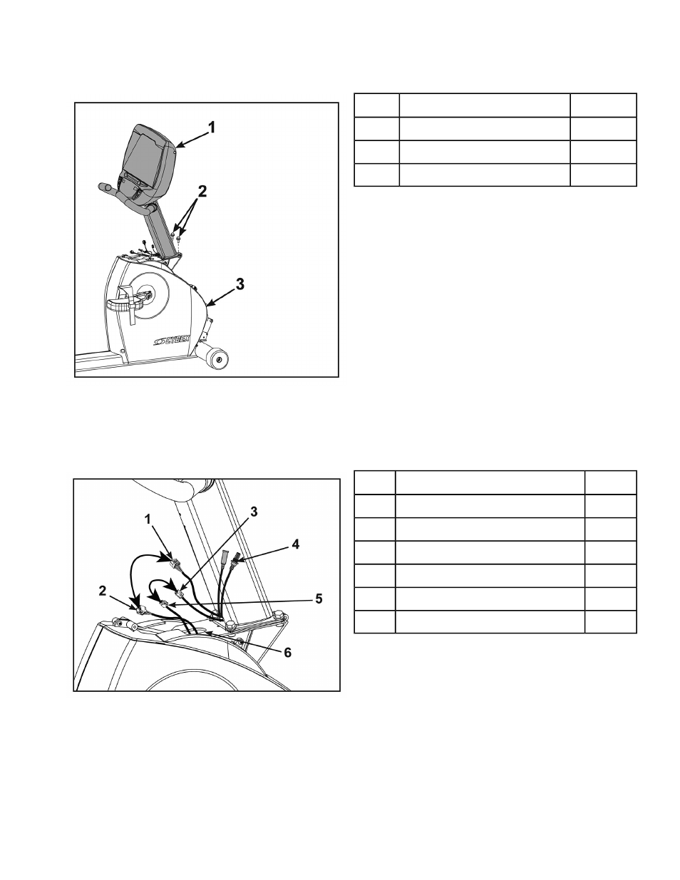
2. Place the console assembly in the correct position on the base assembly by sliding into position
onto the two mounting screws.
Qty.
Description
1
Console Assembly
1
2
Screws
2
1
Base Assembly
3
3. Hand thread the other two screws.
4. Securely fasten the four screws with a 1/2” socket wrench.
5. Plug the upper display cable connector into the lower display cable connector.
Ensure cable connectors click together and are securely fastened.
Qty.
Description
1
Upper Display Connector
1
1
Lower Display Connector
2
1
Upper Heart Rate Connector
3
1
A/V Cables (optional)
4
1
Lower Heart Rate Connector
5
1
Top Hole In Frame
6
6. Plug the upper heart rate connector into the lower heart rate connector.
7. Tuck each of the cable connectors into the top hole in the frame.
Do not pinch or damage the cables during assembly.
Page 24 of 80
Cybex 625C/625R Cycle Part Number LT-23688-4 E