Chapter 3 - installing devices, Removing the chassis cover, Chapter 3 chapter 3 - installing devices – DFI EC700-BT Manual User Manual
Page 11
www.dfi .com
11
Chapter 3 Installing Devices
Chapter 3
Chapter 3 - Installing Devices
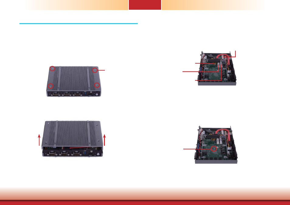
Removing the Chassis Cover
1. Make sure the system and all other peripheral devices connected to it has been powered-off.
2. Disconnect all power cords and cables.
3. The 4 mounting screws on the bottom side of the system are used to secure the cover to the
chassis. Remove these screws and then put them in a safe place for later use.
Mounting Screw
4. After removing the mounting screws, lift the cover up.
Lift the Cover Upward
5. The 3 Mini PCIe slots, the microSD socket and the HDD bracket are readily accessible after
removing the bottom side of the chassis cover.
Full size Mini PCIe slot:
mSATA signal
Half size Mini PCIe slot:
PCIe, USB, and LPC signals for
Wi-Fi module or LPC module
microSD
Full size Mini PCIe slot:
PCIe, USB, and 3G signals
for 3G or GPRS module
6. The SIM slot is readily accessible after removing the screw on the middle of the motherboard
(under the HDD if it has already been installed into the system) and 4 screws on the top side
of the chassis cover.
Mounting Screw
removing the screw on the middle of the motherboard