Chapter 5 – DFI EC700-BT Manual User Manual
Page 27
27
Chapter 5 Ports and Connectors
Chapter 5
www.dfi .com
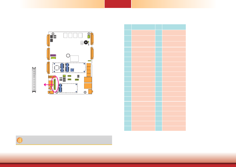
LVDS LCD Panel with Power Connector
3
39
40
LVDS LCD Panel
1
2
The system board allows you to connect a LCD Display Panel by means of the LVDS LCD panel
connector and the LCD/Inverter power connector. These connectors transmit video signals and
power from the system board to the LCD Display Panel.
Refer to the right side for the pin functions of the connector.
BIOS Setting
Configure the LCD panel in the Advanced/Chipset Features submenu of the BIOS. Refer to
chapter 7 for more information.
Pins
Function
Pins
Function
1
GND
2
GND
3
LVDSA_DATA3P
4
LVDSB_DATA3P
5
LVDSA_DATA3N
6
LVDSB_DATA3N
7
GND
8
GND
9
LVDSA_DATA2P
10
LVDSB_DATA2P
11
LVDSA_DATA2N
12
LVDSB_DATA2N
13
GND
14
GND
15
LVDSA_DATA1P
16
LVDSB_DATA1P
17
LVDSA_DATA1N
18
LVDSB_DATA1N
19
GND
20
GND
21
LVDSA_DATA0P
22
LVDSB_DATA0P
23
LVDSA_DATA0N
24
LVDSB_DATA0N
25
GND
26
GND
27
LVDSA_CLKP
28
LVDSA_CLKP
29
LVDSA_CLKN
30
LVDSA_CLKN
31
GND
32
GND
33
LVDS_DDC_CLK
34
Backlight_On_Off
35
LVDS_DDC_DATA
36
+3.3V
37
Backlight Power
38
Dimming
39
Backlight Power
40
Panel Power
Note:
DFI board's LVDS connector: Hirose DF13-40DP-1.25V(91)/40P/1.25mm; cable side
connector: Hirose DF13-40DS-1.25C.