Chapter 4 – DFI EC700-BT Manual User Manual
Page 20
Advertising
www.dfi .com
20
Chapter 4 Jumper Settings
Chapter 4
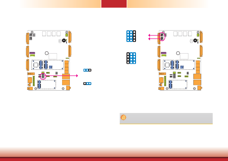
COM 4/DIO Select
1-2, 4-5, 7-8, 10-11 On:
COM 4 (default)
7
9
1
3
10
12
4
6
The system board uses JP21 and JP22 to select between RS232/422/485 COM 4 or isolated
8-bit DIO at the rear panel.
Note:
You cannot use COM 4 and DIO at the same time. Please set up JP21 and JP22
together.
3
JP22
JP21
2-3, 5-6, 8-9, 11-12 On:
DIO
7
9
1
3
10
12
4
6
LCD/Inverter Power Select
3
JP2
1
3
2
1
3
2
2-3 On: +5V
1-2 On: +12V (default)
JP2 is used to select the power level of the LCD/inverter power connector.
Advertising