Hardware installation – DFI ML905-B11C/B16C User Manual
Page 30
Advertising
30
2
Hardware Installation
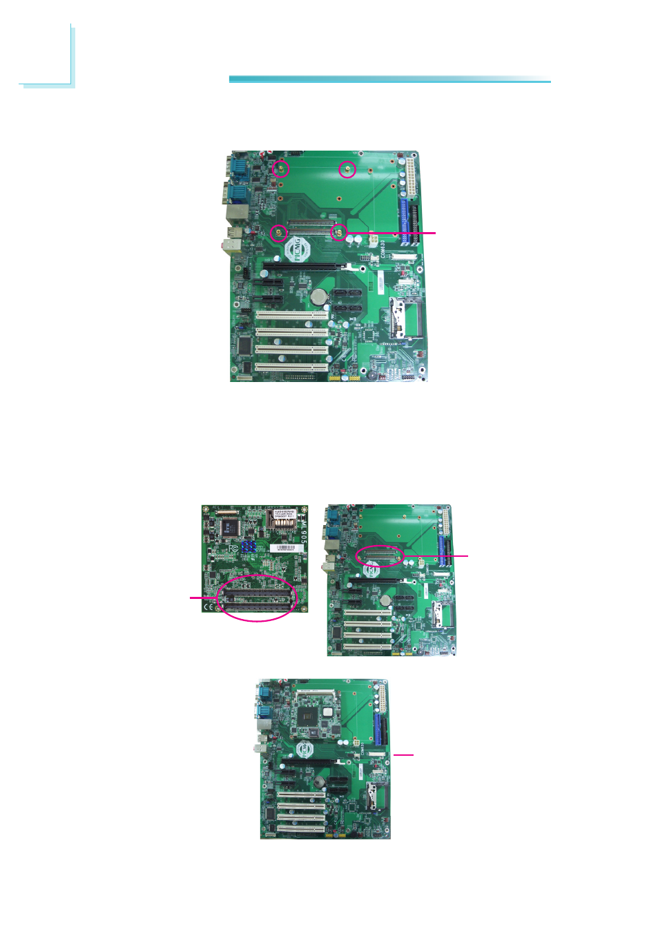
5. The photo below shows the component side of the board with the bolts al-
ready fixed in place.
6. Grasping ML905-B by its edges, position it on top of the carrier board with its
mounting holes aligned with the bolts on the carrier board. This will also align
the COM Express connectors of the two boards to each other.
Press ML905-B down firmly until it is completely seated on the COM Express
connectors of the carrier board.
Bolts
COM Express
connectors on
ML905-B
COM Express
connectors
on the carrier
board
ML905-B installed
on the carrier board
Advertising