Mechanical diagram, Chapter 3 mechanical diagram – DFI HM960-HM86 User Manual
Page 12
Advertising
www.dfi .com
Chapter 3 Hardware Installation
12
Chapter 3
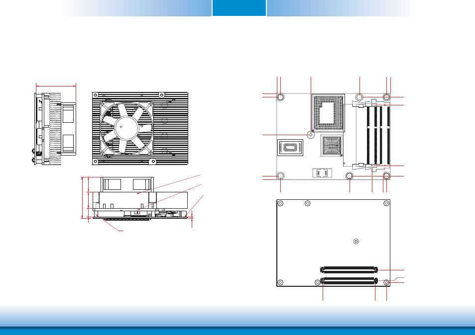
Mechanical Diagram
HM960-QM87/HM86 Module with Heat Sink
Side View of the Module with Heat Sink and Carrier Board
HM960-QM87/HM86 Module
53.00
2.00
Heat sink and fan
Module PCB
standoff
55.00
20.00
22.00
11.00
Heat spreader
Top View
0.00
0.00
4.08
45.61
91.08
4.08
95.15
12.84
79.64
91.08
4.
08
37
.48
91.08
121.08 125.15
4.
08
80.08
121.08
104
.85
119.07
2.00
0.00
14.00
12.50
0.00
70.20
Bottom View
Advertising
This manual is related to the following products: