System memory, Jumper settings – DFI CD952 series User Manual
Page 10
www.dfi .com
10
Chapter 2 Hardware Installation
Chapter 2
System Memory
DDR3
Features
•
2GB DDR3 onboard (standard)
- Intel
®
Atom
TM
D2550/N2800 supports up to 4G (optional)
Important:
Electrostatic discharge (ESD) can damage your board, processor, disk drives, add-in
boards, and other components. Perform installation procedures at an ESD workstation
only. If such a station is not available, you can provide some ESD protection by wear-
ing an antistatic wrist strap and attaching it to a metal part of the system chassis. If
a wrist strap is unavailable, establish and maintain contact with the system chassis
throughout any procedures requiring ESD protection.
Important:
When the Standby Power LED lit red, it indicates that there is power on the system
board. Power-off the PC then unplug the power cord prior to installing any devices.
Failure to do so will cause severe damage to the motherboard and components.
Standby
Power LED
VGA
1
VGA
/
DVI-I
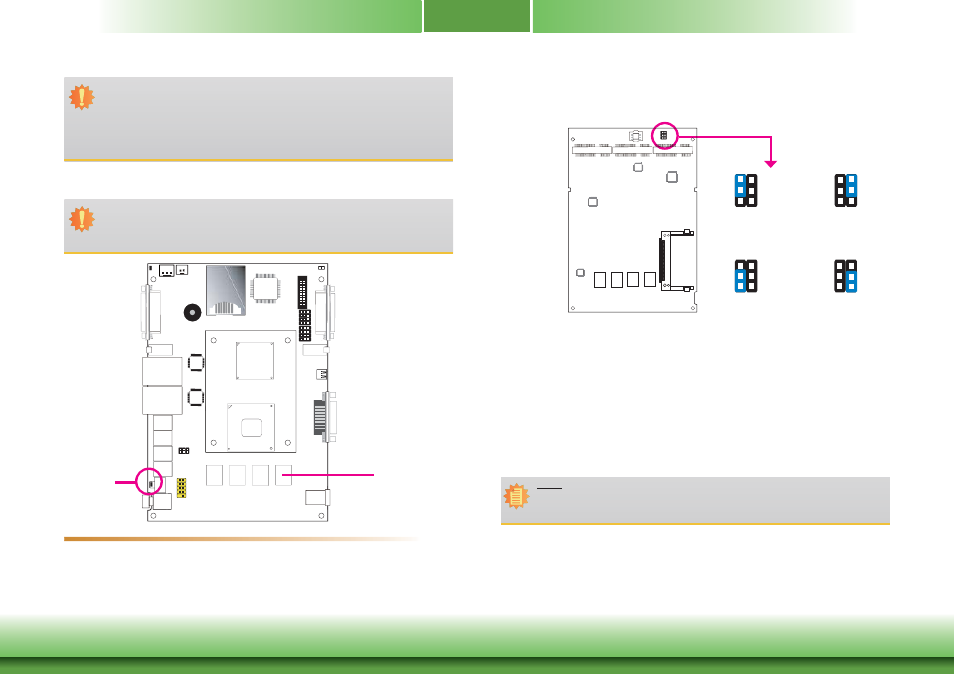
Jumper Settings
Power-on/Clear CMOS
JP5
1-3 On: Power-on via
power button (default)
6
4
2
5
3
1
6
4
2
5
3
1
3-5 On: Auto Power-on
Power-on
JP5 is used to select the method of powering on the system. If you want the system to pow-
er-on whenever AC power comes in, set JP5 pins 3 and 5 to On. If you want to use the power
button, set pins 1 and 3 to On.
When using the JP5 “Power On” feature to power the system back on after a power failure
occurs, the system may not power on if the power lost is resumed within 5 seconds (power
flicker).
Note:
In order to ensure that power is resumed after a power failure that re covers within a
5 second period, JP5 must be set to pins 3-5 and the “AC Power Lose” in CMOS is set
to “On”.
2-4 On: Normal
(default)
6
4
2
5
3
1
6
4
2
5
3
1
4-6 On: Clear CMOS