Chapter 2 – DFI CD952 series User Manual
Page 11
www.dfi .com
11
Chapter 2 Hardware Installation
Chapter 2
Clear CMOS
If you encounter the following,
a) CMOS data becomes corrupted.
b) You forgot the supervisor or user password.
you can reconfigure the system with the default values stored in the ROM BIOS.
To load the default values stored in the ROM BIOS, please follow the steps below.
1. Power-off the system and unplug the power cord.
2. Set JP5 pins 4 and 6 to On. Wait for a few seconds and set JP5 back to its default setting,
pins 2 and 4 On.
3. Now plug the power cord and power-on the system.
USB Power Select
VGA
1
VGA
/
DVI-I
These jumpers are used to select the power of the USB ports. Selecting +5V_standby will
allow you to use a USB device to wake up the system.
USB 0-3
Important:
If you are using the Wake-On-USB Keyboard/Mouse function for 2 USB ports, the
+5V_standby power source of your power supply must support
≥1.5A. For 3 or more
USB ports, the +5V_standby power source of your power supply must support
≥2A.
2-4 On: +5V
6
4
2
5
3
1
4-6 On: +5V_standby
(default)
1-3 On: +5V
3-5 On: +5V_standby
(default)
JP8
USB 4-5
6
4
2
5
3
1
6
4
2
5
3
1
6
4
2
5
3
1
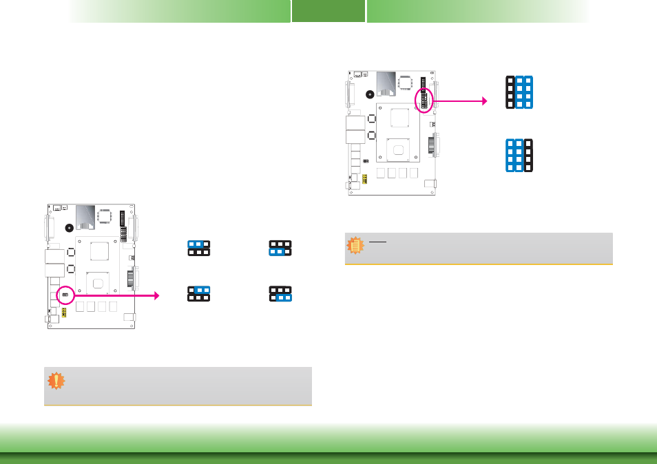
COM2/DIO Select
VGA
1
VGA
/
DVI-I
1-4-7-10, 2-5-8-11
On: COM2 (default)
JP9 and JP10
6
4
3
1
12
10
9
7
6
4
3
1
12
10
9
7
2-5-8-11, 3-6-9-12
On: DIO
The system board uses JP9 and JP10 to select between RS232/422/485 COM2 or isolated 4-bit
DIO at the rear panel.
Note:
You cannot use COM2 and DIO at the same time. Please set up JP9 and JP10 at the
same time.