Appendix e – DFI CD952 series User Manual
Page 65
Advertising
www.dfi .com
65
Appendix E Digital I/O User Guide
Appendix E
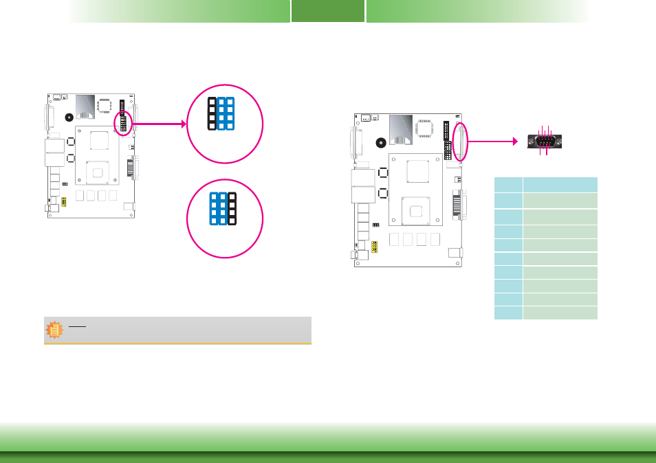
CD952 Series: Isolated 4-bit Digital I/O Jumper Setting
COM2/DIO Select
VGA
1
VGA
/
DVI-I
1-4-7-10, 2-5-8-11
On: COM2 (default)
JP9/JP10
6
4
3
1
12
10
9
7
6
4
3
1
12
10
9
7
2-5-8-11, 3-6-9-12
On: DIO
The system board uses JP9 and JP10 to select between RS232/422/485 COM2 or isolated 4-bit
DIO at the rear panel.
Note:
You cannot use COM2 and DIO at the same time. Please set up JP9 and JP10 at the
same time.
COM port mode
DIO mode
CD952 Series: Isolated 4-bit Digital I/O Pin Define
VGA
1
VGA
/
DVI-I
COM2 (Serial) Port/ Isolated 4-bit DIO
RS232/422/485 COM2
or Isolated 4-bit DIO
Pins
DIO Function
1
DIN0A
2
DIN0B
3
DIN1A
4
DIN1B
5
GND
6
DOUT0A
7
DOUT0B
8
DOUT1A
9
DOUT1B
1
2
3
4
5
6
7
8
9
Advertising