Block diagram, Mechanical diagram, Chapter 2 block diagram mechanical diagram – DFI CD952 series User Manual
Page 9: Nm10
Advertising
www.dfi .com
9
Chapter 2 Hardware Installation
Chapter 2
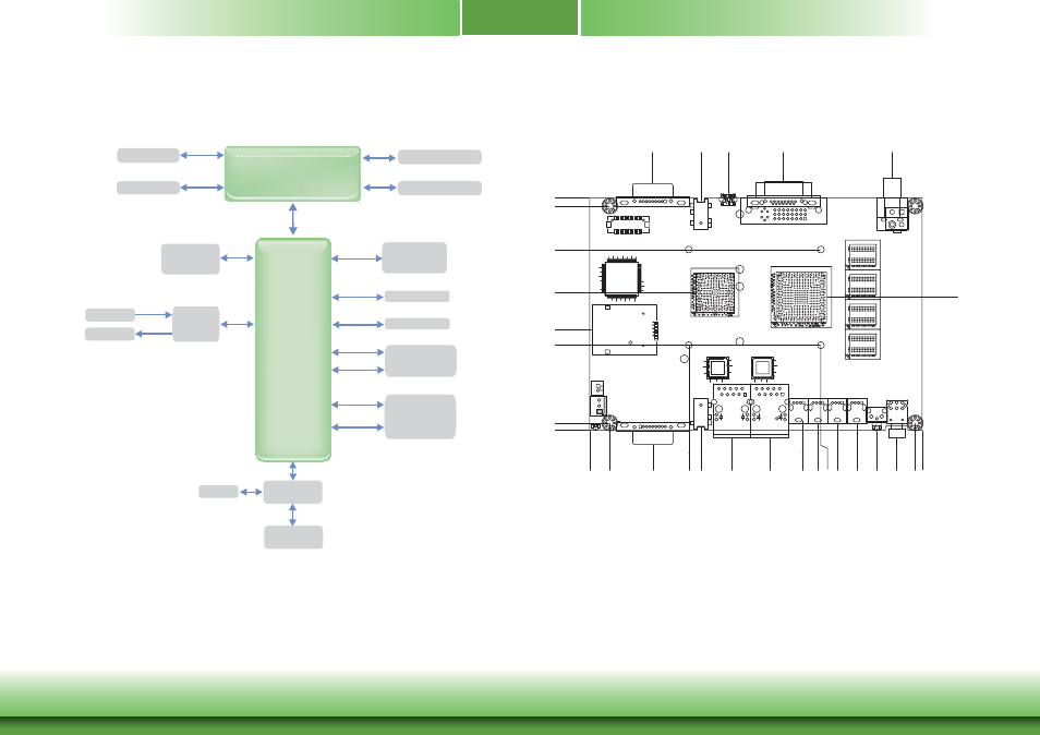
Block Diagram
Mechanical Diagram
NM10
PCIe
3G with SIM
(Mini PCIe)
PCIe
Intel GLAN
2x
DDR3 Onboard
SATA
CFAST
USB 6x
CK505
DC-IN
Codec
USB 2.0
DDR3
VGA/DVI
DMI
HDA
L/R out
LINE-OUT
MIC-IN
L/R in
SATA
mSATA
(Mini PCIe)
USB
PCIe
Wi-Fi/BT with
LPC Bus
(Mini PCIe)
USB
SUPER IO
COM 2x
DIO
RS232/422/485
Atom D2550
Atom N2800
Atom N2600
DVI-I
0.00
8.90
27
.7
6
62.50
79.00
43.53
101.53
93.35
100.27
108.
77
117
.27
126.04
134
.80
142.90 146.00
0.00
3.20
44.21
60.54
37.32
79.32
98.40
102.00
27
.7
2
48.89
48.89
60.90
85.16
132.80
58.47
Advertising