I/o connectors, Chapter 2 i/o connectors – DFI CD952 series User Manual
Page 19
www.dfi .com
19
Chapter 2 Hardware Installation
Chapter 2
I/O Connectors
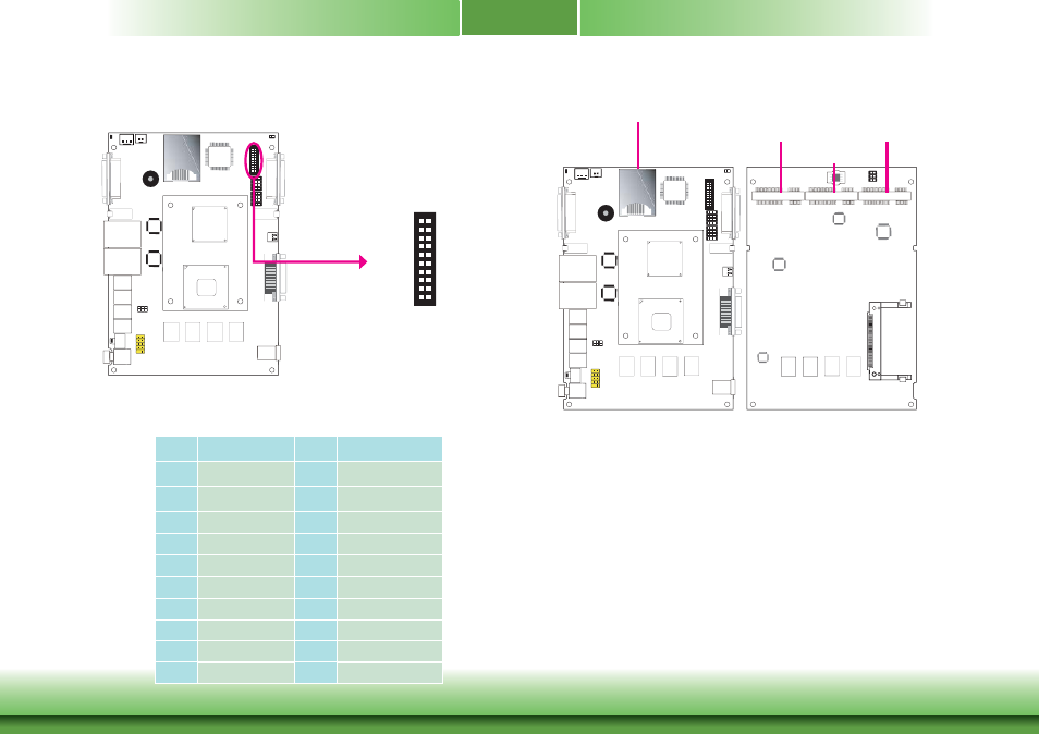
The 8-bit Digital I/O connector provides powering-on function to external devices that are con-
nected to these connectors.
Digital I/O Connector (optional)
Digital I/O Connector
VGA
1
VGA
/
DVI-I
1
2
19
20
4-bit in and 4-bit out
DIO with power
Pins
Function
Pins
Function
1
DIN0A
2
DOUT0A
3
DIN0B
4
DOUT0B
5
DIN1A
6
DOUT1A
7
DIN1B
8
DOUT1B
9
DIN2A
10
DOUT2A
11
DIN2B
12
DOUT2B
13
DIN3A
14
DOUT3A
15
DIN3B
16
DOUT3B
17
+5V
18
+5V_standby
19
GND
20
GND
Expansion Slots
SIM Slot
The SIM slot on the system board is used to insert a SIM card.
Mini PCI Express Slot
The Mini PCI Express slot on the system board is used to install a half and/or full size Mini
PCIe card such as network cards or other cards that comply to the mini PCI Express specifica-
tions into the mini PCI Express slot.
VGA
1
VGA
/
DVI-I
SIM slot
Mini PCIe for
mSATA
Mini PCIe slot for
PCIe x1, USB, and 3G
signals
Mini PCIe slot for
PCIe x1, USB, and Wi-Fi
signals