Appendix e – DFI CD952 series User Manual
Page 67
Advertising
www.dfi .com
67
Appendix E Digital I/O User Guide
Appendix E
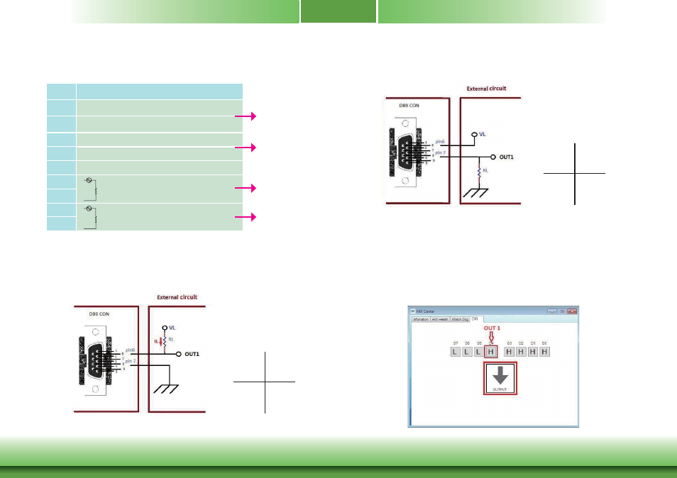
4-bit (2-bit in and 2-bit out) description
DOUT Example1 with Dout0A/Dout0B
VL: 60V max
IL max: 600mA
For example:
VL= 5V
RL= 1K
Ω
IL= 5mA
DFI DIO
Utility D4
OUT1
H
L
L
H
DOUT Example2 with Dout0A/Dout0B
DFI DIO
Utility D4
OUT1
H
L
H
L
Set DIO at Output Mode, Press D4 to H
Example1 OUT1 to Low.
Example2 OUT1 to High.
Pins
Input Request
*
1
5V~12V
2
GND
*
3
5V~12V
4
GND
5
GND
*
6
Loading AC or DC 5V~60V
7
*
8
Loading AC or DC 5V~60V
9
AC or DC
Load
AC or DC
Load
Pin 1 and 2 are
couple, DIN1
Pin 3 and 4 are
couple, DIN2
Pin 6 and 7 are
couple, OUT1
Pin 8 and 9 are
couple, OUT2
Advertising