DFI SB630-CRM User Manual
Page 56
56
2
Hardware Installation
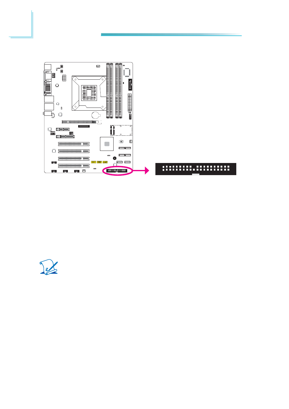
IDE Connector
The IDE connector is used to connect hard drives. The connector on the IDE
cable can be inserted into this connector only if pin 1 of the cable is aligned with
pin 1 of this connector.
The IDE connector supports 2 devices, a Master and a Slave. Use an IDE ribbon
cable to connect the drives to the system board. An IDE ribbon cable has 3 con-
nectors on them, one that plugs into the IDE connector on the system board and
the other 2 connects to IDE devices. The connector at the end of the cable is for
the Master drive and the connector in the middle of the cable is for the Slave
drive.
Note:
Refer to your disk drive user’s manual for information about selecting
proper drive switch settings.
Adding a Second IDE Disk Drive
When using two IDE drives, one must be set as the master and the other as the
slave. Follow the instructions provided by the drive manufacturer for setting the
jumpers and/or switches on the drives.
The system board supports Enhanced IDE or ATA-2, ATA/33, ATA/66, ATA/100
and ATA/133 hard drives. We recommend that you use hard drives from the
same manufacturer. In a few cases, drives from two different manufacturers will
not function properly when used together. The problem lies in the hard drives,
not the system board.
40
39
2
1