Installation, Top vent venting requirements, Installation of top vent dv – Montigo M40DV CL CR User Manual
Page 10
P/N XG0206
Page 10
M40DV-CR/CL Corner Gas Fireplace
Top Vent Venting Requirements
Before you install any venting, you must determine whether the
venting run will be acceptable. Unacceptable venting can affect the
fireplace's combustion.
for installations with horizontal venting runs of 0-16 feet, use the
vent graph, as described below
the maximum horizontal vent run is 16 feet.
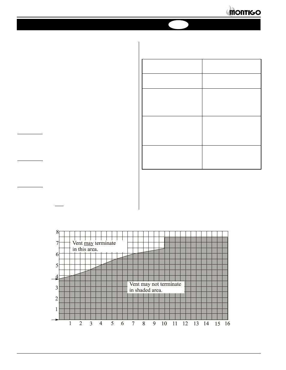
The Rear Vent Venting Graph
Measure the vertical height from the fireplace hearth to the centre of
the termination and the horizontal run from the from the fireplace flue
collar to the wall flange of the termination. Plot on the Venting Graph
(Fig. 12) with an 'X'.
If the 'X' falls on or above the top boundary of the shaded area, the
installation is acceptable.
Example A: (Acceptable Installation)
If the vertical dimension from the hearth is 72", and the hori-
zontal run to the wall flange of the vent termination is 120", this
would be an acceptable installation.
Example B: (Acceptable Installation)
If the vertical dimension from the hearth is 66" and the horizontal
run to the wall flange of the vent termination is 30", this would be
an acceptable installation.
Example C: (Unacceptable Installation)
If the vertical dimension from the floor of the fireplace is 48" and
the horizontal run to the wall flange of the vent termination is
84",
this would NOT be an acceptable installation.
Installation Of Top Vent DV
A complete
M40DV-CR/CL vent system may comprise up to five dif-
ferent types of components:
A - Termination
PTO-3 (3" length)
PTO-3F (3" length)
B - Stucco Kits
MSR (stucco frame)
MOSR (stucco can)
C - Flex sections
PFL-1 (12" section)
PFL-2 (24" section)
PFL-3 (36" section)
PFL-4 (48" section)
D - Solid sections
PEXT-1 (12" section)
PEXT-2 (24" section)
PEXT-3 (36" section)
PEXT-4 (48" section)
E - Elbows
PEL-90MM (m/m 90° el-
bow)
PEL-90FF (f/f 90° elbow)
Installation
Top Vent
Figure 12. Rear Vent Venting Graph.
Height to center
of vent pipe.
Hearth
Vent Rise (feet)
Vent Run (feet)