Installation, Horizontal vent installation – Montigo M40DV CL CR User Manual
Page 8
P/N XG0206
Page 8
M40DV-CR/CL Corner Gas Fireplace
Installation
Short Configurations:
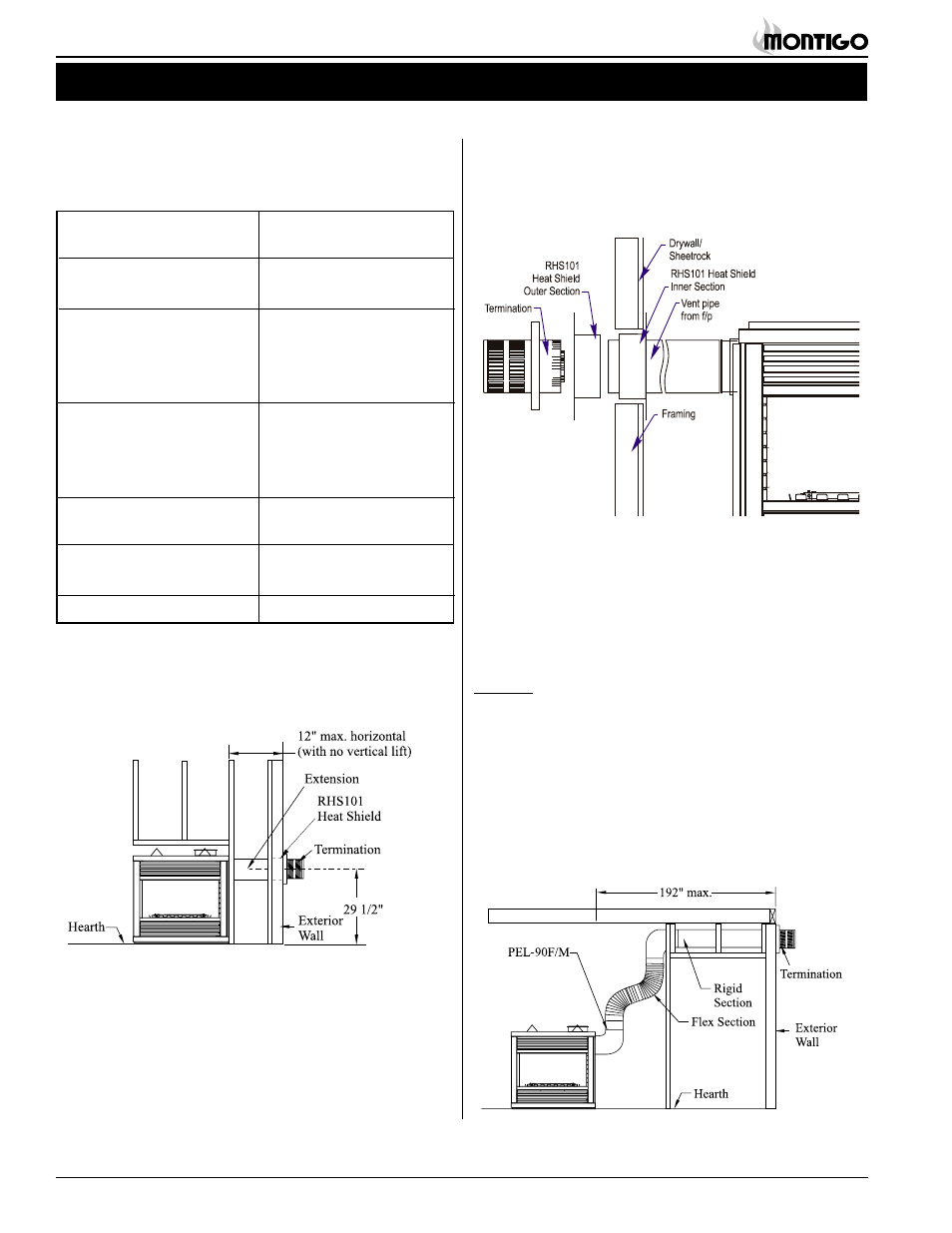
For installations straight through the wall, use an PTO-3/-3F termina-
tion and PXT-5 or PXT-10 to achieve the desired length. The maxi-
mum horizontal vent run with no vertical lift is 12". See Figure 7.
Example:
A 10' section of rigid pipe and a 90° elbow may be used in conjunc-
tion with a 3 ft. flex section (PFL-3) will, when extended in a chase,
allow for a maximum horizontal run of twelve and one-half feet from
the centre of the fireplace to outside wall and a minimum of 7'6" when
retracted in opposite direction.
(See Figure 9.)
"D" flex sections and "E" solid sections may be used in conjunction
with one another to obtain different possible horizontal length instal-
lations.
NOTE: Flex section must not exceed maximum horizontal
length of 3 feet, and for this application the top clearance is to the
Long Vent Runs:
For longer or more complex vent runs, vertical lift is required. First
ensure that the planned run is acceptable using the Vent Graph. Plan
out the required components using the chart above. You may be able
to use fewer components using the chart below.
Figure 7. Short horizontal installation.
Figure 9. Extended horizontal installation using a combination of rigid
and flex venting.
Figure 8. Heat Shield for short horizontal installation. Install by sliding
over the vent pipe where it connects to the termination.
Heat Shields
Due to high flue temperatures, the heat shield (RHS101) must be
used on
all installations straight through the wall, at the point
where the vent pipe connects to the termination. With the heat shield,
vent clearances can be maintained at 1". The heat shield is not
included with the fireplace.
To install the heat shield, slide one section over the vent pipe on the
inside of the wall opening, with the circular portion
inside the wall cav-
ity. Screw the shield in place over the wall opening. Install the second
section on the outside of the wall opening sliding the circular portion
into the wall opening. Refer to Figure 8.
Horizontal Vent Installation
Vent systems that terminate through a wall may comprise up to seven
different components:
A - Termination
PTO-3
PTO-3F
B - Stucco Kits
MSR (stucco frame)
MOSR (stucco can)
D - Flex sections
PFL-1 (12" section)
PFL-2 (24" section)
PFL-3 (36" section)
PFL-4 (48" section)
E - Rigid sections
PEXT-1 (12" section)
PEXT-2 (24" section)
PEXT-3 (36" section)
PEXT-4 (48" section)
F - Extensions
PXT- 5 (5" section)
PXT-10 (10" section)
G - 90° elbow
PEL-90F/F
PEL-90M/M
H - Heat Shield
RHS101 ( for 5"/8" venting)