Installation, Venting requirements – Montigo M40DV CL CR User Manual
Page 7
Page 7
P/N XG0206
M40DV-CR/CL Corner Gas Fireplace
Venting Requirements
If your installation requires more than 12" of horizontal venting, some
vertical lift is required. Use the vent graph below to determine an
acceptable vent run. Unacceptable venting can affect the fireplace's
performance.
the maximum horizontal vent run is 16 feet
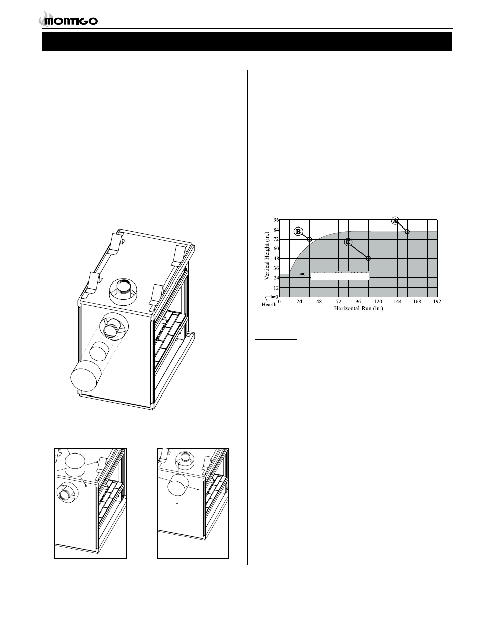
The Venting Graph
Measure the vertical height from the fireplace hearth to the centre of
the termination and the horizontal run from the from the fireplace flue
collar to the wall flange of the termination. Plot on the Venting Graph
(Fig. 6) with an 'X'.
If the 'X' falls on or above the top boundary of the shaded area, the
installation is acceptable.
Figure 6. Venting Graph.
Example A: (Acceptable Installation)
If the vertical dimension from the hearth is 82", and the hori-
zontal run to the wall flange of the vent termination is 156", this
would be an acceptable installation.
Example B: (Acceptable Installation)
If the vertical dimension from the hearth is 72" and the horizontal
run to the wall flange of the vent termination is 36", this would be
an acceptable installation.
Example C: (Unacceptable Installation)
If the vertical dimension from the floor of the fireplace is 48" and
the horizontal run to the wall flange of the vent termination is
108",
this would NOT be an acceptable installation.
Center of vent 29½"
Converting to Top Vent/ Rear
Vent (Installing the Flue Cover)
Rear Vent
An M40DV-CR/CL is shipped ready for a rear vent installation.
1. The outer flue cover must be secured in place with a minimum of
2 screws as shown below.
Top Vent
The flue cover may be converted for a top vent installation.
1. Remove the inner and outer flue covers from the top vent flue
collar.
2. Install both the inner and outer flue covers on the rear vent flue
collar as shown in figure 5a.
3. The outer flue cover must be secured in place with a minimum of
Figure 5a. Installing the flue cover.
Figure 5b. Flue cover installation
for rear vented fireplace.
Figure 5c. Flue cover installation
for top vented fireplace.
Installation