Electrical system • 24hfu – MovinCool 24HFU Service Manual User Manual
Page 13
MOVINCOOL 24HFU / 24HFU-1 SERVICE
PAGE 13
ELECTRICAL SYSTEM • 24HFU
4-1.
Basic Operation of MovinCool Modelp 24HFU Electrical Circuit
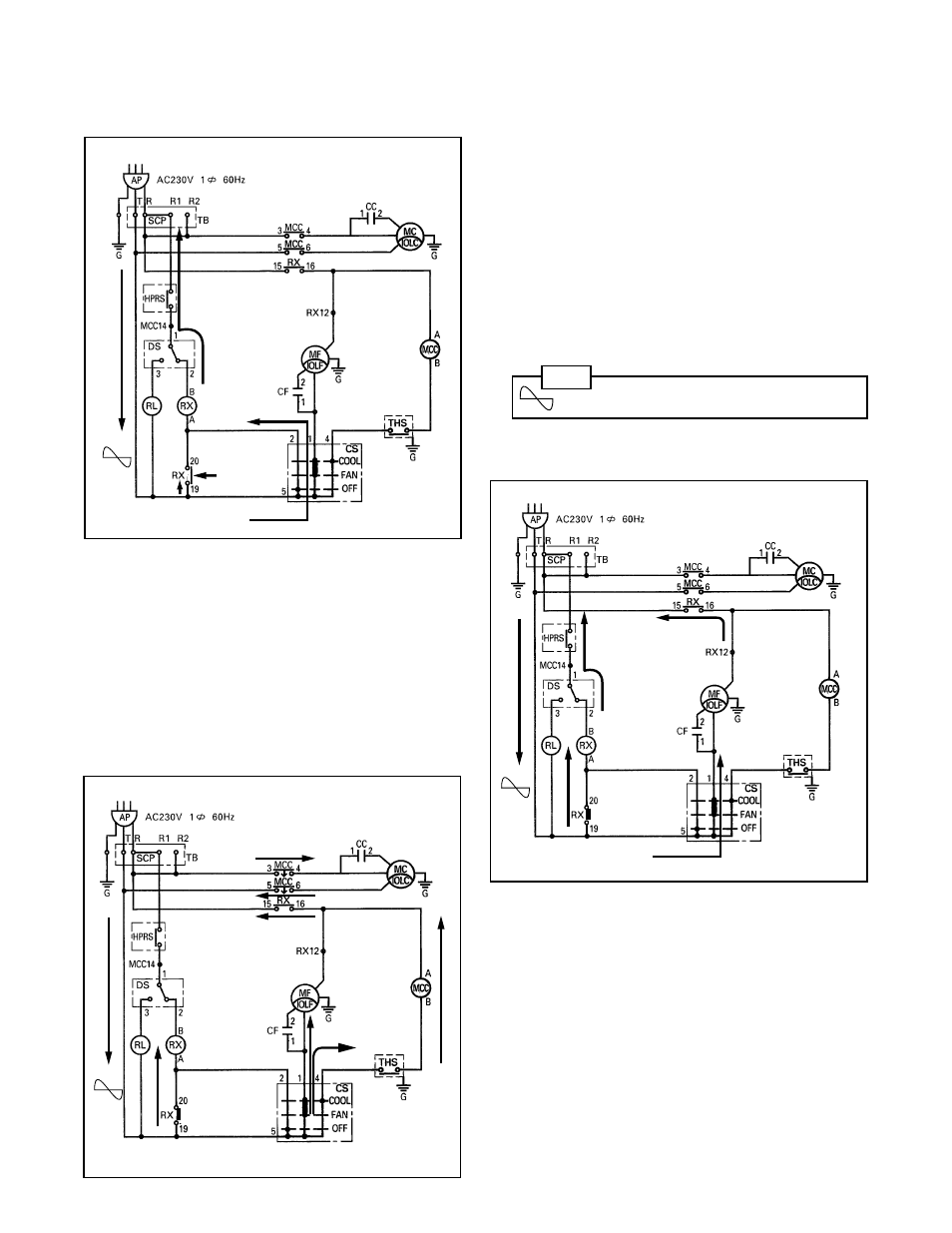
The three basic modes of operation are as follows:
1) Control Switch in “OFF” position:
a. Current flows through terminals 5 and 2
of the control switch (CS) and to the coil
of the auxiliary relay (RX). (A and B.)
b. Two contacts (RX) of the auxiliary relay
are closed by electromagnetic force. The
closed contact RX (terminals 19 and 20)
allows current to flow directly to the
auxiliary relay coil and hold the contact in
a closed position.
■ Operation in “OFF” position
2) Control Switch in “FAN” position:
a. Current also flows through the control
switch (CS) to the fan motor (MF).
b. Current flows through the contact (termi-
nals 19 and 20) of the auxiliary relay and
its coil, and remains closed.
■ Operation in “FAN” position
NOTE
Symbol indicates alternating current.
3) Control Switch in “COOL” position:
a. The contacts of the auxiliary relay remain
closed as mentioned in step 2) b.
b. Current flows to the fan motor (MF).
c. Current also flows to the anti-freezing
thermostat (THS) contact, to the coil of
the relay for the compressor motor
(MCC) (A and B) and the auxiliary relay
contacts.
d. Two contacts of the relay for the com-
pressor motor (MCC) are closed by the
electromagnetic force. Current then
flows to the compressor motor (MC).
■ Operation in “COOL” position