Electrical system • 24hfu – MovinCool 24HFU Service Manual User Manual
Page 15
MOVINCOOL 24HFU / 24HFU-1 SERVICE
PAGE 15
ELECTRICAL SYSTEM • 24HFU
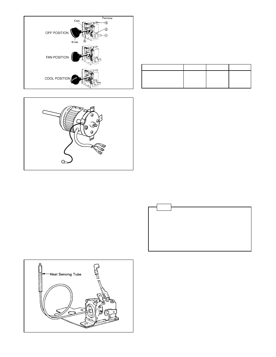
4-3.
Control Switch
The control switch is employed to start or stop
operation. This switch is a 250V, 20A rating
rotary type (3-position). The switching positions
are OFF-FAN-COOL. Each contact is switched
by the cam uniting with the shaft.
Switch Terminals
OFF
FAN
COOL
(5) - (2)
Conduct
OFF
OFF
(5) - (1)
OFF
Conduct
OFF
(5) - (4)
OFF
Conduct
Conduct
■ Control Switch
CF1
CF2
RX12
■ Fan Motor
■ Thermostat
4-4.
Fan Motor
The fan motor is a single phase, induction type
motor which drives fans on the evaporator side
and the condenser side at the same time.
Specifications:
Rated Voltage
AC 230V
Rated Output
552 Watts
UL Listed File No.
E49807
4-5.
Compressor Motor
The compressor motor is a single phase motor
and is contained within the same housing as the
compressor.
Specifications:
Rated Voltage
AC 230V
Rated Output
1600 Watts
NOTE
An internal overload relay is used to protect the
compressor motor and fan motor. This relay is
built into the compressor motor and fan motor and
will interrupt the flow of current when there is an
overcurrent situation or if abnormally high
temperature builds up in the compressor motor or
fan motor.
4-6.
Anti-freezing Thermostat
If the evaporator has frosted, the thermostat
contacts open to stop the compressor and the
unit continues to operate on “FAN” mode. Once
the evaporator has defrosted, the contacts close
to restart the compressor and the unit operates
in “COOL” mode. The thermostat heat sensing
tube is mounted at the evaporator outlet tube
and is insulated from surrounding air by heat
insulating material. The thermostat contacts are
opened at -1.5˚C and closed at +14.5˚C.