Electrical system • 24hfu – MovinCool 24HFU Service Manual User Manual
Page 16
MOVINCOOL 24HFU / 24HFU-1 SERVICE
PAGE 16
ELECTRICAL SYSTEM • 24HFU
4-7.
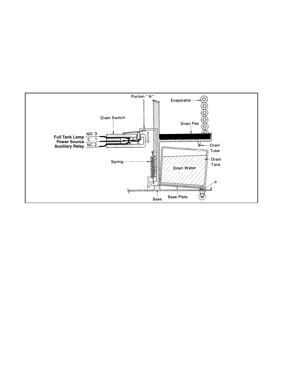
Drain Switch
The drain switch interrupts both the compressor motor circuit and the fan motor circuit when the drain water
accumulates approximately 4.4 gallons (16 liters) in the drain tank. This also illuminates the full tank lamp
on the control panel and stops the operation. This system adopts a 250V, 3A rating micro switch for this
function. When drain water accumulates approx. 4.4 gallons (16 liters) in the drain tank, the drain tank base
plate, which is supported at its fulcrum (a), is pushed down in the arrow direction as shown in the figure
below. When the drain tank base plate is forced down, “portion A” located at the top of the drain tank base
plate turns off the contacts (1) - (2) of the micro switch. Since this breaks the auxiliary relay (RX) circuit, the
auxiliary relay contacts are turned off to break the compressor circuit and the fan motor circuit. At the same
time, the contacts (1) - (3) are turned on to light the full tank warning lamp.
■ Operation of Drain Switch
When the drain tank is removed (or the water in the drain tank is drained), portion “A” of the drain tank base
plate returns to its original position by the elasticity of the coil spring. Then the contacts (1) - (3) turn off,
extinguishing the full tank lamp. At the same time, the contacts (1) - (2) turn on. Under this condition, turn
the control switch to FAN or COOL position to start operation.
4-8.
Condensate Pump Kit <OPTIONAL>
Models 24HFU and 24HFU-1 come standard with a condensate tank, which collects the water that forms on
the evaporator during normal cooling operation. If the unit is required to operate continuously without
periodic emptying of this tank, a condensate pump may be needed. A condensate pump kit is available for
Models 24HFU and 24HFU-1.