Electrical system • 24hfu-1 – MovinCool 24HFU Service Manual User Manual
Page 20
MOVINCOOL 24HFU / 24HFU-1 SERVICE
PAGE 20
ELECTRICAL SYSTEM • 24HFU-1
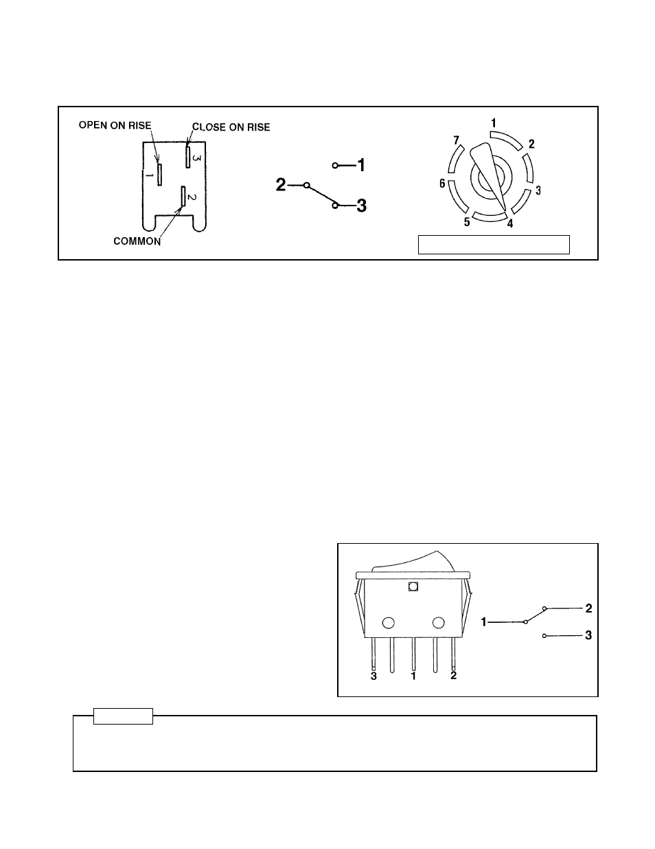
4-3.
Temperature Control
The compressor is controlled by a thermostat which senses the return air temperature. This thermostat can
be set to approximate temperatures by means of the thermostat dial, located below the control switch.
1 LESS COOL
→
7 COOLEST
4-4.
Fan Mode Control Switch
The fan motor is controlled by a switch located in the control box. There are two positions:
A. COOL-OFF
When the switch is set to the left, the fan motor is controlled by the thermostat which controls the
compressor. In this case, both the fan and the compressor stop when the thermostat detects suffi-
ciently low intake air temperature. When the temperature increases again, the fan will restart automati-
cally. The fan motor is independent from the time delay circuit which protects the compressor, conse-
quently the fan will begin approximately 75 seconds before the compressor restarts.
B. COOL-FAN
When the switch is set to the right, the fan motor will be controlled only by the control switch. As long
as the unit is set to FAN or COOL, the fan will operate continuously. (This is the factory default setting.)
Specifications:
Rated Voltage
AC 240V
Rated Current
20 amps (Power Factor COS r = 1)
Off
16.1
±
1.1 (˚C)
Diff
2.8
±
1.1 (˚C) (ON: 18.9 (˚C))
UL Listed File No.
SA512
CAUTION
Because there is a built-in delay circuit to protect the compressor, the compressor will never start up immedi-
ately, regardless of the type of operation. This delay is part of the normal operation of Model 24HFU-1 and
should not be diagnosed as a malfunction.
Specifications:
Rated Voltage
AC 250V
Rated Current
16 amps
UL Listed File No.
E98133