ONICON D-100 Flow User Manual
Page 9
11451 Belcher Road South, Largo, FL 33773 • USA • Tel +1 (727) 447-6140 • Fax +1 (727) 442-5699 • [email protected]
D-100 Flow Display Manual 10/14 - 0634-14 / 18340
Page 9
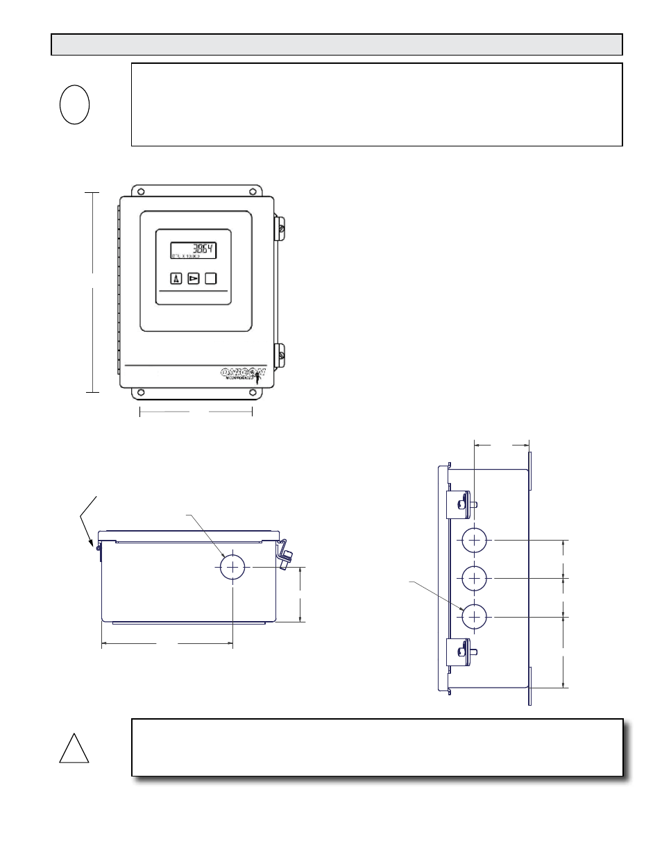
SCROLL RESET PROGRAM
10 3/4”
6”
D-100
CAUTION
Do not drill additional holes in this enclosure. Doing so may damage the electronic circuitry
contained within and will void all warranties.
!
3.2 MECHANICAL INSTALLATION
3.2.1 Main Unit Installation
2.500
1.750
1.750
3.250
3X 01.115
01.115
2.500
6.000
CONDUIT HOL LOCATION
BOTTOM VIEW
HINGE SIDE
SOWN FOR REFERENCE.
CONDUIT HOL LOCATION
RIGHT SIDE VIEW
• Find an easily accessible location where electrical
connections can be made and meter readings can be
taken from the floor level.
• Mount the display on a vibration-free surface. Avoid
sites such as the plenum of a fan coil, heat exchanger,
or other housings containing motors. Do not install the
display in direct sunlight.
Use four screws for mounting the display. The
mounting surface must be structurally sound and
capable of withstanding a minimum weight of 40lbs
(18kg). Use the following screws for mounting.
• (4) Machine screws - HHMS .25-20 x 1.5”
• (4) Wood screws - FHLS .25 x 1.5”
• (4) Concrete screws - HHCS .25 x 1.5”
i
IMPORTANT NOTE
The ONICON D-100 Display is a custom calibrated system. Unless specifically noted in writing
by ONICON, ALL COMPONENTS (Display and flow meter) share the same serial number and
must be installed together as a system. Mixing components from different systems will result in
significant errors in calibration.