Three phase ups systems 1. system overview – OnLine Power Battery Backup System User Manual
Page 15
OLP
Three Phase UPS Systems
1. SYSTEM OVERVIEW
1-11
Usually, the most frequent failures of the UPS occur at the inverter. Therefore, the
UPS has redundant protection circuitry to protect the inverter. A strong snubber is added
to suppress the spikes and noise, oversized high quality components are used
throughout, semi-conductor fuses are provided, and ventilation is maximized. The
result of this design is a more rugged, reliable and high efficient inverter. At the same
time, the inverter can sustain overload and high peak current drawn by the load.
Additionally, a longer MTBF is achieved.
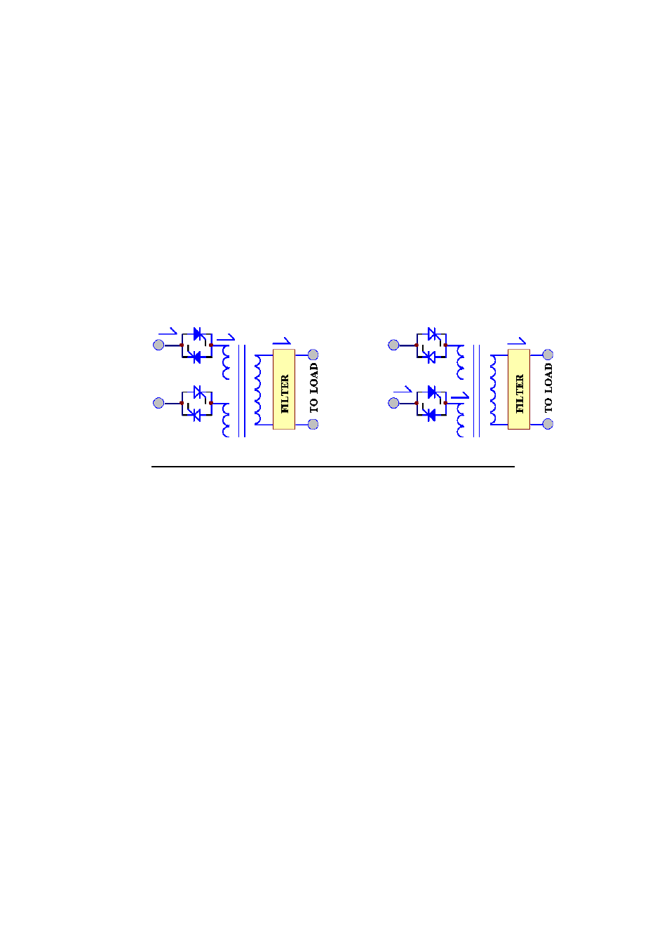
1.5. Static Switch
RESERVE
INVERTER
RESERVE
INVERTER
RESERVE MODE
INVERTER MODE
The static switch is composed of two pairs of SCR's, connected back-to-back. The
switch transfers the load from reserve to inverter or from inverter to reserve without
losing power at the output. It is a very important portion of a UPS.
Custom detection and logic circuitry is incorporated to achieve a zero dead time
transfer of the static switch module. If the output exceeds the inverter rating, the
static switch will be invoked to protect the inverter providing that the input voltage
and frequency are within safe limits for the load. If the output is short circuited, the
UPS will shut down to protect the inverter and the reserve power circuitry.
Following any transfer, the CPU performs a check for validation of successful
transfer.