On-line power – OnLine Power Phase Stabilizer User Manual
Page 23
On-Line Power
6002-032 REV H
1-14
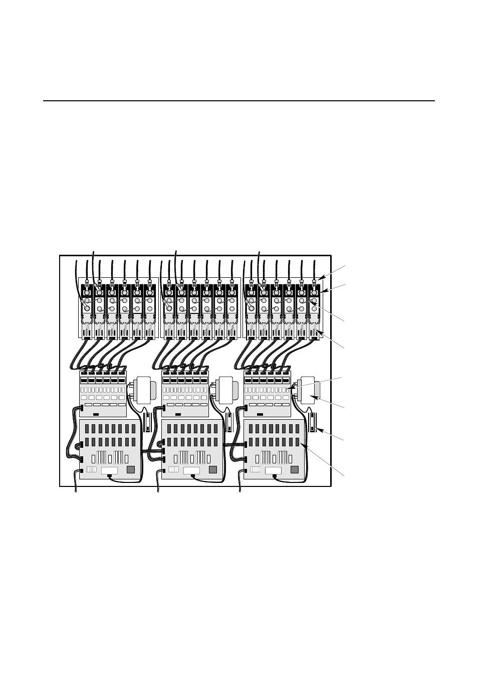
1-5 REGULATION
COMPONENTS
Regulation is accomplished by solid-state electronics which control the tap switching function at the zero-
current-crossing. Refer to Section NO TAG, THEORY OF OPERATION for more detail.
The regulation components are mounted on the regulation panel and can be seen by removing the front panel.
See Illustration 1-11 and 1-12. The regulation components include 3 SCR Control logic boards, 3 SCR Driver
boards, 18 SCR/SCR Snubber board assemblies, 3 current transformers, 3 reference transformers, and 3
heatsinks. See Illustration 1-13 for a block diagram of the regulation panel components.
Each SCR Control logic board has seven LEDs. The first six LEDs indicate the active tap selection during
operation. LED 7 indicates power is applied to the board and is always lit during operation.
6
6
5
5
4
4
3
3
2
2
1
1
6
6
5
5
4
4
3
3
2
2
1
1
6
6
5
5
4
4
3
3
2
2
1
1
HEATSINK (3)
SCR (18)
FUSELINK (15)
SCR SNUBBER
BOARD (18)
SCR DRIVER
BOARD (3)
FUSES FOR
REF. TRANSFORMER (3)
(NOT ON ALL MODELS)
REFERENCE
TRANSFORMER (3)
To
Current
Transformer
To
Current
Transformer
To
Current
Transformer
To Bypass
To Bypass
To Bypass
SCR CONTROL
LOGIC BOARD (3)
REGULATION PANEL ASSEMBLY LAYOUT (TYPICAL ONLY)
ILLUSTRATION 1-11