Touble-shooting and customer service – REMKO RVS 60 H User Manual
Page 15
The system has been manufactured using state-of-the-art production methods and in house tested many times to
ensure the system is 100% in working order. If malfunctions should occur, please check the system as detailed in
the list below. For installations with an indoor-outdoor system, observe the chapter “Trouble-shooting and customer
service” in both operating manuals.
Please inform your dealer if the system is still not working correctly after all the function checks have been per-
formed.
Touble-shooting and customer service
Malfunctions
Please note that this trouble-shooting table continues on the next page
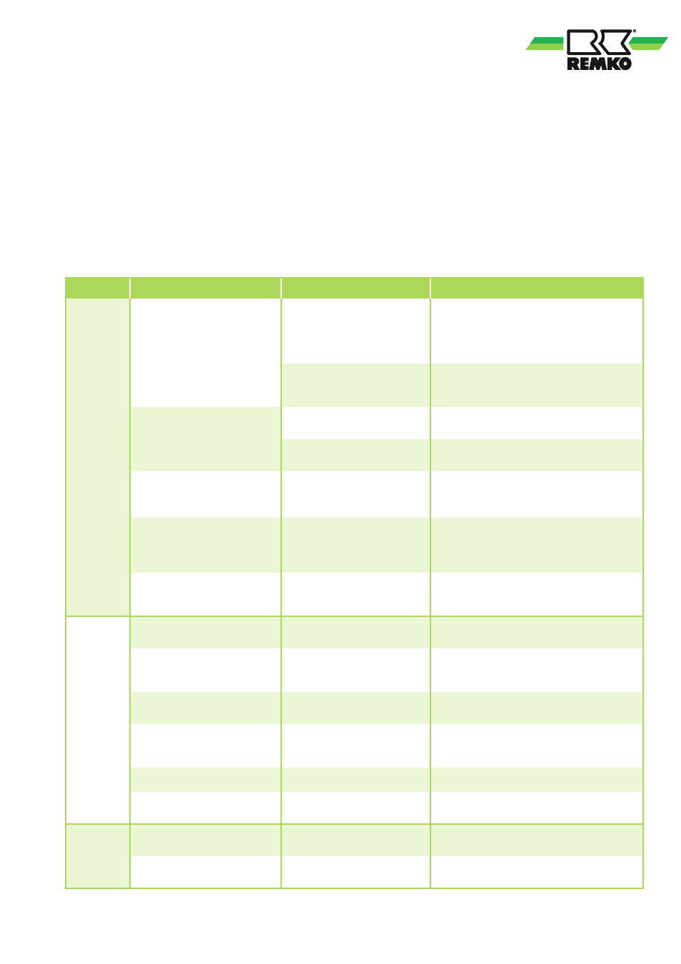
Fault
Possible cause
Check
Remedial measures
The unit
does not
start
Display is not illuminated.
No power supply
Check the power connections at the mains
and the voltage values.
Check breaker switches/fuses at the second-
ary side of the supplemental transformer.
Incorrect phase sequence.
The KA3 phase sequence relay
did not enable.
Replace power supply phase conductorat the
at the terminal strip on the switch panel.
The display is illuminated but
the unit does not start.
Unit in STAND BY
See paragraph "Key functions" for the acti-
vation of the unit.
No external enabling contact
is shortened
Check connection to the GND - ID5 termi-
nals.
The unit does not start, the
compressor icon in the display
is blinking.
Start-up delay
Wait out the start-up delay (max 360 sec.),
the compressor should then start.
The display blinks and
alternately shows an
alphanumeric code and the
temperature value.
One or more protective
devices have responded
Check which safety device has responded,
correct the cause of the fault and reset the
safety device (see "Fault display by code")
Compressor overload switch is
activated.
Does the compressor icon light
up and does the switch have
voltage?
Have specialist replace switch or compressor.
The unit
is work-
ing with
reduced
cooling/
heating
capacity
Thermal load was increased.
Have there been any structural
changes?
Maintain safety clearances.
Supply temperature too high
(cooling) / too low (heating).
If the medium outlet tempera-
ture is approx. 5 ... 10 °C /
35 ... 40 °C?
Increase/reduce medium intake temperature.
Air in the medium cycle.
Are automatic bleeders in-
stalled at the highest point?
Bleed manually or install automatic bleeders.
Condenser / evaporator tem-
peratures too high (cooling) /
too low (heating).
Are the fins clean / free of ice
and the operating limits
complied with?
Comply with operating limits
Cooling: Clean fins, provide shade for the
unit, heating: Reduce supply temperature
Incorrect parameter setting.
Check setting.
Change setting.
Pulse mode because of too
little demand.
Is the system oversized?
Increase medium flow with the installation of
a storage tank.
Medium
discharge
Leak in the lines or insulation
defective.
Are there leaks and are all of
the lines insulated?
Seal and insulate.
Defrosting phase in heating
mode.
Heating mode set?
Normal operating status.
15