Sound pressure level – REMKO RVS 60 H User Manual
Page 41
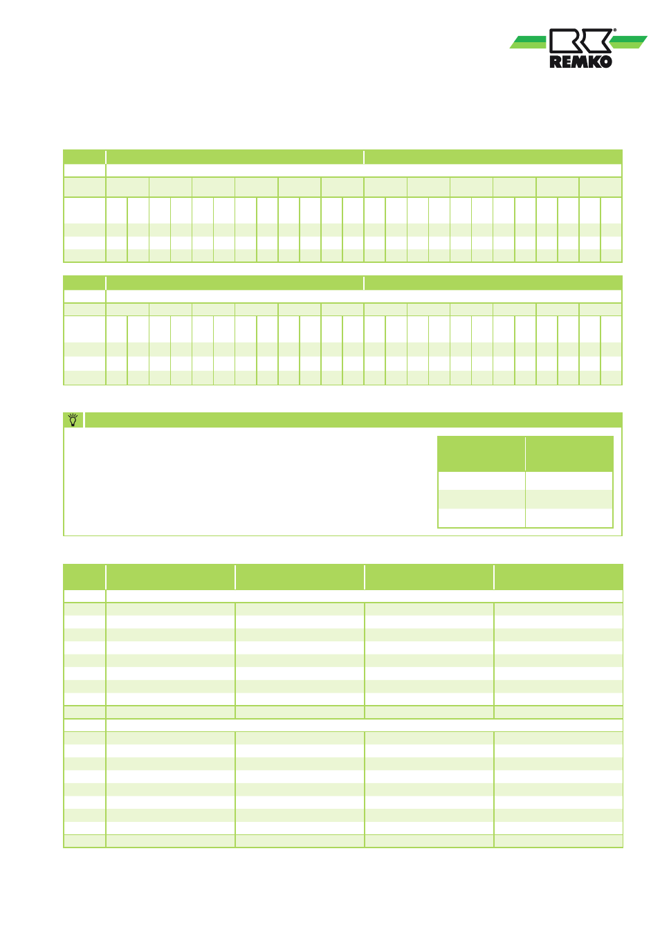
RVS 60H
RVS 75H
RVS 100H
RVS 150H
Hz
Sound pressure level Lp in dB(A), distance 1m
63
29,9
29,0
31,4
32,1
125
37,2
36,8
39,8
40,2
250
48,1
48,1
51,1
51,2
500
54,2
54,0
56,9
57,5
1000
56,8
57,4
59,8
60,0
2000
58,2
59,1
61,6
61,2
4000
53,3
54,4
56,5
56,3
8000
44,5
47,8
48,8
47,5
Total
62,3
63,1
65,5
65,4
Hz
Sound pressure level Lp in dB(A), distance 10m
63
9,9
9,0
11,4
12,1
125
17,2
16,8
19,8
20,2
250
28,1
28,1
31,1
31,2
500
34,2
34,0
36,9
37,5
1000
36,8
37,4
39,8
40,0
2000
38,2
39,1
41,6
41,2
4000
33,3
34,4
36,5
36,3
8000
24,5
27,8
28,8
27,5
Total
42,3
43,1
45,5
45,4
41
RVS 60H
RVS 75H
Air intake temperature / relative air humidity
°C/%r.F.
-5 / 90
0 / 90
+5 / 85
+7 / 85
+10 / 85 +15 / 80
-5 / 90
0 / 90
+5 / 85
+7 / 85
+10 / 85 +15 / 80
Medium
intake
Q
H
kW
P
E
kW
Q
H
kW
P
E
kW
Q
H
kW
P
E
kW
Q
H
kW
P
E
kW
Q
H
kW
P
E
kW
Q
H
kW
P
E
kW
Q
H
kW
P
E
kW
Q
H
kW
P
E
kW
Q
H
kW
P
E
kW
Q
H
kW
P
E
kW
Q
H
kW
P
E
kW
Q
H
kW
P
E
kW
35
5,07 1,79 5,74 1,91 6,42 2,02 6,88 2,10 6,99 2,12 7,38 2,23 6,22 2,42 7,12 2,52 8,03 2,62 8,70 2,68 9,41 2,72 10,51 2,88
40
4,91 1,83 5,56 1,94 6,22 2,05 6,68 2,13 6,79 2,15 7,18 2,26 6,03 2,46 6,91 2,56 7,80 2,66 8,48 2,72 9,16 2,76 10,21 2,91
45
4,75 1,87 5,38 1,97 6,02 2,08 6,48 2,16 6,59 2,18 6,97 2,30 5,84 2,50 6,71 2,59 7,58 2,69 8,25 2,75 8,90 2,79 9,91 2,94
RVS 100H
RVS 150H
Air intake temperature / relative air humidity
°C/%r.F.
-5 / 90
0 / 90
+5 / 85
+7 / 85
+10 / 85 +15 / 80
-5 / 90
0 / 90
+5 / 85
+7 / 85
+10 / 85 +15 / 80
Medium
intake
Q
H
kW
P
E
kW
Q
H
kW
P
E
kW
Q
H
kW
P
E
kW
Q
H
kW
P
E
kW
Q
H
kW
P
E
kW
Q
H
kW
P
E
kW
Q
H
kW
P
E
kW
Q
H
kW
P
E
kW
Q
H
kW
P
E
kW
Q
H
kW
P
E
kW
Q
H
kW
P
E
kW
Q
H
kW
P
E
kW
35
8,49 3,53 9,97 3,68 11,46 3,82 12,27 3,90 12,76 3,94 13,77 4,14 14,14 4,24 15,73 4,56 17,32 4,88 18,27 5,12 18,98 5,22 20,47 5,54
40
8,20 3,62 9,68 3,76 11,15 3,90 11,94 3,98 12,41 4,01 13,39 4,21 13,69 4,36 15,23 4,69 16,77 5,02 17,74 5,26 18,49 5,35 20,00 5,67
45
7,92 3,71 9,38 3,85 10,85 3,99 11,60 4,05 12,05 4,08 13,00 4,29 13,24 4,48 14,73 4,83 16,23 5,17 17,20 5,40 17,99 5,48 19,52 5,79
Nominal medium flow; 0% glycol concentration; Q
H
= heating capacity
Heating capacity
Ice forms on the fins in heating mode as a consequence of the heat
absorption. The amount of ice depends on the percentage of
humidity in the ambient air. Under certain cycles and
temperature conditions, defrosting cycles are run through in which
no heat capacity can be generated. The following reduction fac-
tors for the defrosting cycles must be taken into account even when
planning the layout:
NOTE
Ambient
temperature
Reduction
factor
+5
0,94
0
0,88
-5
0,89
Sound pressure level
RVS 60H to RVS 150H: Air intake temperature TK 35°C, medium intake 12 °C, medium outlet 7 °C, 0% glycol concentration, hemisphere rating under
Free field conditions