Remko rvs...h (inox) – REMKO RVS 60 H User Manual
Page 20
RVS 60H
RVS 75H
RVS 100H
RVS 150H
A
250
250
350
350
B
250
300
350
400
C
1000
1200
1500
1500
D
600
600
800
800
E
600
600
700
700
All values in mm
■
Comply with any regulations
and conditions affecting the
structure of the building. If
necessary, use sound reducing
material.
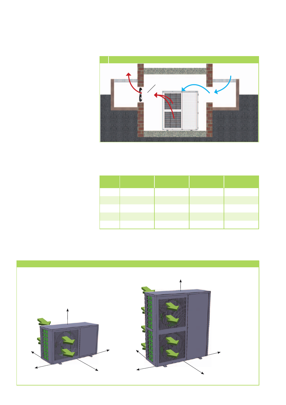
Warm air
Cold
fresh air
Light
well
Chiller
Warm air
Light
well
Additional
fan
5 Installation inside buildings (cooling mode)
Minimum clearances
The following illustration indicates
the minimum clearances for trou-
ble-free operation of the system.
These protection zones serve to
ensure unrestricted air intake and
discharge, as well as providing suf-
ficient room for performing main-
tenance and repairs and prevent-
ing the unit from being damaged.
Minimum clearances
RVS 60H / RVS 75H
RVS 100H / RVS 150H
C
B
A
D
E
C
B
A
D
E
REMKO RVS...H (INOX)
20