REMKO RVS 60 H User Manual
Page 31
Pr
obe intake
High pr
essur
e switch
Pr
obe output
Low pr
essur
e switch
Four
-way-r
everseing
alve
Enable contact
potential fr
ee
O
pe
ra
tin
g
co
nt
ac
t C
-H
po
te
nt
ia
l f
re
e
General fault signal
potential fr
ee
Pr
obe condenser
Flow switch
24V
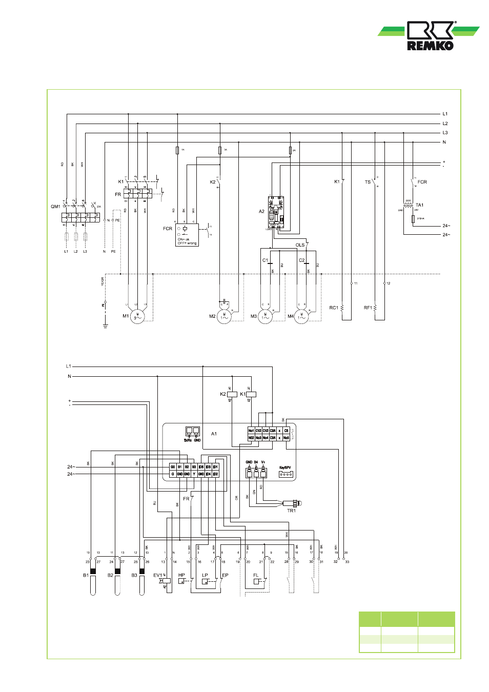
Legend:
A1 Controller
A2 Fan speed controller
B1 Probe medium intake
B2 Probe medium outlet
B3 Probe condenser
EV Reverse flow valve
FCR Phase sequence relay
FL Flow switch
FR Motor overload protection switch
HP High pressure switch
LP Low pressure switch
M1 Compressor
M2 Circulation pump
M3 Condenser fan 1
M4 Condenser fan 2
RC1 Compressor crank case heater
RF1 Defrost heater
TA1 Transformer 230/24V
TR1 Pressure transducer
TS Temperature controller
TX1 Thermal contact fan 1
TX2 Thermal contact fan 2
RVS 100H / RVS 150H
RVS 100H / RVS 150H
Compressor
Pressure transducer
Circulation pump
Controller
Condenser
fan 1
Condenser
fan 2
Crank case
heater
Defrost
heater
Colour code:
BU blue
BR brown
BK black
GR Green
RT red
OR orange
WT white
YE yellow
YE/GR yellow/green
RVS 100H RVS 150H
K 1
7.5kW
7.5kW
FR
13A
18A
QM 1
20A-D3
20A-D3
31