Remko heat pump manager – REMKO Multi-talent Plus User Manual
Page 56
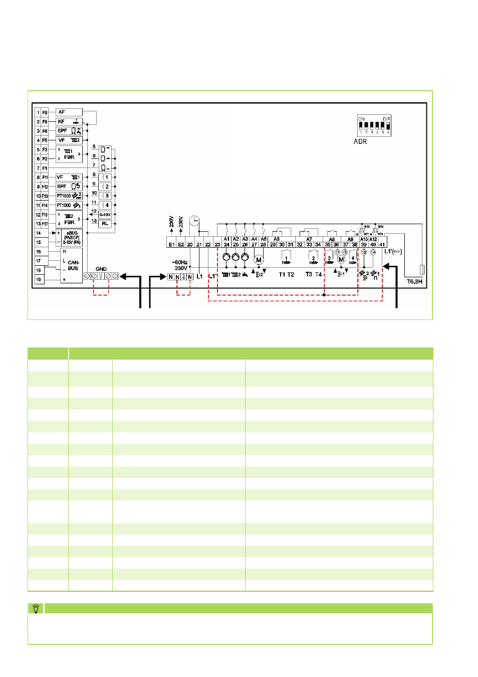
REMKO Heat Pump Manager
Contact layout Merlin I/O circuit board (solder side view)
Please also note the connection diagrams or the electrical circuit diagrams for the installed heat pump.
These are found in the respective installation manual.
NOTE
Terminal
Sensor no.
Description
Note
1
F9
External sensor
2
F8
Collector sensor (collective supply)
Heating control sensor
Heating control sensor. Must be located in accordance with the
system diagram!
3
F6
Hot water sensor
4
F5
Supply sensor HC 2 (mixer circuit)
5
F3
not assigned
6
F2
not assigned
7
F1
not assigned
8
F11
Supply sensor WP or HC 1
HC 1 is a direct heating circuit
9
F12
Sensor storage tank bottom
Reference sensor solar or solid-fuel boiler
10
F13
Sensor solid fuel boiler
Pt 1000
11
F14
Sensor solar collector
Pt 1000
12
F15
Flow volume sensor
Impulse input
13
F17
Return sensor (cooling control sensor)
is found as set in the factory in the indoor unit. Depending on the
selected (hydraulic) system, the sensor may have to be mounted
at a different position
14
eBUS +
Signal output 0-10 V
Modulation depth (target output in %)
15
eBus -
Signal output 0-10 V
Modulation depth (target output in %)
16
CAN-Bus H
17
CAN-Bus L
18
CAN-Bus -
19
CAN-Bus +
Remko specific contact layout for the circuit board inputs
56